
China Stainless Steel

stainless steel
low fin tube

TeCarve’s Stainless Steel Low Fin Tube is specifically designed to enhance heat transfer efficiency by increasing the external surface area without enlarging the overall tube diameter.

These tubes are widely used in air-cooled heat exchangers, condensers, chillers, and evaporators across HVAC, power generation, petrochemical, and refrigeration industries. Made from high-grade stainless steel, they offer excellent corrosion resistance, mechanical durability, and thermal conductivity even under harsh operating conditions.

The integrally formed low fins ensure compact design, longer service life, and reduced fouling. Custom fin height, pitch, and base tube materials are available to match your precise technical requirements.

Stainless steel finned tube for HVAC and heat exchanger applications
Enhanced Heat Transfer Tubing

High-Efficiency Thermal Transfer: Integral Stainless Low Fin Tubes on ASTM A213 / A249

1
A498-Type Integral Rolled Fins: External helical fins rolled on ASTM A213 / A249 base tubes with custom plain land ends.
2
Controlled Wall Under Fin: Monitored during rolling per A498-type practice (min wall within +18%, average within ±9%).
3
Rigorous NDT & Hydrostatic: 100% hydrostatic and eddy-current tested with standard EN 10204 3.1 MTC.
MOQ
Trial batches from 100–300 kg to support heat exchanger prototyping and retubing
Lead Time
Standard base tube sizes: 7–10 days; custom alloy finning: 10–25 days
Samples
Standard finned tube samples dispatched within 48 hours (freight collect)
Documents
EN 10204 3.1 MTC standard; 100% hydrostatic & eddy-current tested per order

Specifications

Available Specifications by Standard Matrix

Scope & Markets: Base tube to ASTM A213 (seamless) / ASTM A249 (welded) — fin geometry is TeCarve commercial specification, confirmed per order drawing

Base OD (in / mm)Fin Density (FPI)Fin PitchFin HeightRoot Dia.Min Wall under FinArea Ratio (β)Fin OD (d_fin)Tolerances
3/4" (19.05 mm)19 FPI1.34 mm1.35 mm16.20 mm1.10 mm2.65×≤ 19.05 mm (-0.15)OD ±0.10mm | FPI ±1
3/4" (19.05 mm)26 FPI0.98 mm1.10 mm16.80 mm0.95 mm3.10×≤ 19.05 mm (-0.15)OD ±0.10mm | FPI ±1
3/4" (19.05 mm)28 FPI0.91 mm0.95 mm17.10 mm0.90 mm3.35×≤ 19.05 mm (-0.15)OD ±0.10mm | FPI ±1
3/4" (19.05 mm)32 FPI0.79 mm0.85 mm17.30 mm0.85 mm3.55×≤ 19.05 mm (-0.15)OD ±0.10mm | FPI ±1
1" (25.40 mm)19 FPI1.34 mm1.45 mm22.30 mm1.40 mm2.75×≤ 25.40 mm (-0.15)OD ±0.10mm | FPI ±1
1" (25.40 mm)26 FPI0.98 mm1.15 mm22.90 mm1.20 mm3.15×≤ 25.40 mm (-0.15)OD ±0.10mm | FPI ±1
1" (25.40 mm)28 FPI0.91 mm1.00 mm23.20 mm1.10 mm3.40×≤ 25.40 mm (-0.15)OD ±0.10mm | FPI ±1
5/8" (15.88 mm)19 FPI1.34 mm1.20 mm13.40 mm0.90 mm2.55×≤ 15.88 mm (-0.12)OD ±0.10mm | FPI ±1
5/8" (15.88 mm)26 FPI0.98 mm1.00 mm13.80 mm0.80 mm3.00×≤ 15.88 mm (-0.12)OD ±0.10mm | FPI ±1
1/2" (12.70 mm)26 FPI0.98 mm0.80 mm11.00 mm0.70 mm2.90×≤ 12.70 mm (-0.10)OD ±0.10mm | FPI ±1
1-1/4" (31.75 mm)19 FPI1.34 mm1.30 mm28.95 mm1.65 mm2.70×≤ 31.75 mm (-0.18)OD ±0.15mm | FPI ±1
1-1/2" (38.10 mm)19 FPI1.34 mm1.30 mm35.30 mm1.90 mm2.65×≤ 38.10 mm (-0.20)OD ±0.15mm | FPI ±1

Fin geometry above is TeCarve commercial specification, not an ASTM-specified value (fin count, pitch and height are agreed between purchaser and supplier). Following A498-type practice: Outside diameter over fins (d_fin) is cold-rolled strictly to not exceed the plain end outer diameter (d_plain), so tubes are dimensioned to pass through TEMA standard baffle holes and tubesheets for direct retubing; fit is confirmed against your tubesheet drawing on request. Root wall thickness can be specified to meet ASME Section VIII UG-27 minimum pressure design requirements for a stated design pressure, confirmed per order on request. Fin density tolerance: ±1 FPI (±2% pitch); Fin height tolerance: ±0.05 mm; Plain end OD tolerance per ASTM A1016 Table 3.

Scope & Markets: N. America — Cold-drawn seamless (A213) & welded (A249) base tube mechanical & dimensional matrix

Base OD (mm)Base WT Range (mm)Fin Height (mm)FPI SelectionsSeamless WT Tol. (A213)Welded WT Tol. (A249)
12.70 (1/2")0.89 – 1.240.8019, 26±10% (Cold Formed)Min Wall (-0%) / +20%
15.88 (5/8")1.00 – 1.651.0019, 26, 28±10% (Cold Formed)Min Wall (-0%) / +20%
19.05 (3/4")1.24 – 2.111.10 – 1.3519, 26, 28, 32±10% (Cold Formed)Min Wall (-0%) / +20%
22.20 (7/8")1.24 – 2.111.10 – 1.3519, 26, 28±10% (Cold Formed)Min Wall (-0%) / +20%
25.40 (1")1.65 – 2.771.15 – 1.4519, 26, 28±10% (Cold Formed)Min Wall (-0%) / +20%
31.75 (1-1/4")2.11 – 3.051.3016, 19, 26±10% (Cold Formed)Min Wall (-0%) / +20%
38.10 (1-1/2")2.11 – 3.401.3016, 19, 26±10% (Cold Formed)Min Wall (-0%) / +20%

Base tube outside diameter tolerances comply with ASTM A1016/A1016M-14 Table 3. Seamless tubes are bright annealed or solution annealed per ASTM A213. Each welded tube is subjected to either a hydrostatic test or a nondestructive electric test per ASTM A249/A249M Section 13.6; the purchaser may specify which test is used.

Scope & Markets: Europe & International — Metric integral low-fin heat exchanger tubing (EN 10216-5 / EN 10217-7)

Metric OD (mm)Base WT (mm)Fin Height (mm)Fin Density (FPI / Pitch)ISO 1127 OD Tol.ISO 1127 WT Tol.
12.01.00.826 FPI (0.98 mm)±0.15 mm (D3)±10.0% (T3)
16.01.21.026 FPI (0.98 mm)±0.15 mm (D3)±10.0% (T3)
19.0 / 20.01.51.219 FPI (1.34 mm)±0.20 mm (D3)±10.0% (T3)
25.02.01.419 FPI (1.34 mm)±0.19 mm (D4)±10.0% (T3)
30.0 / 32.02.51.316 FPI (1.59 mm)±0.24 mm (D4)±10.0% (T3)

Base tube delivery conditions per EN 10216-5 TC1/TC2 for seamless stainless steel and EN 10217-7 for welded stainless steel. Metric tolerances comply with EN ISO 1127 Class D3/T3 and precision Class D4/T4.

Scope & Markets: Japan & East Asia — Stainless steel low-fin heat exchanger & boiler tubes

Base OD (mm)Base WT (mm)Fin Height (mm)FPI SelectionsJIS OD ToleranceJIS WT Tolerance
12.701.200.824, 26±0.20 mm±10%
15.881.20 – 1.501.019, 26±0.20 mm±10%
19.051.651.219, 26, 28±0.20 mm±10%
25.402.101.319, 26±0.25 mm±10%
31.802.601.316, 19±0.30 mm±10%

Manufactured per JIS G3463 (stainless steel boiler and heat exchanger tubes) and JIS G3459 (stainless steel pipes). Each tube is subjected to either a hydrostatic test or a non-destructive examination (ultrasonic or eddy current), as required by JIS G3463 / JIS G3459.

Scope & Markets: China & Belt-and-Road — Integral finned boiler & heat exchanger tubes

Base OD (mm)Base WT (mm)Fin Height (mm)Fin Density (FPI)GB OD ToleranceGB WT Tolerance
12.01.00.824, 26±0.12 mm±10%
16.01.21.022, 26±0.16 mm±10%
19.01.51.219, 26, 28±0.19 mm±10%
25.02.01.419, 26±0.25 mm±10%
32.02.51.316, 19±0.30 mm±10%

Conforms to GB/T 13296 (seamless stainless steel tubes for boiler and heat exchanger) and GB/T 24593 (welded austenitic stainless steel tubes for heat exchanger).

  • Supply Length / Form: Fixed straight lengths 1–12 m; precision U-bent tubes with plain or finned bend portions.
  • Available Grades: Austenitic 304, 304L, 316, 316L, 321; Duplex 2205 (UNS S31803 / S32205); Super Austenitic 904L.
  • Fin Geometry: Integral cold-rolled fins, 16 to 32 FPI; fin height 0.8–1.45 mm; trapezoidal profile with 5°–10° draft angle.
  • Standard Compliance: Base tube ASTM A213, ASTM A249, EN 10216-5, JIS G3463, GB/T 24593; finned tube reference DIN 28178. Finning inspection follows the ASTM A498/A498M framework (A498 itself covers low-carbon steel base tubes).

Heat Transfer Area Expansion Matrix & Fin Density Selection

Low fin tubes enhance heat duty by expanding the external surface area relative to plain tube (OD 19.05 mm baseline = 0.0598 m²/m). Selection of fin density balances available surface area against shell-side fluid fouling and pressure drop:

Fin ConfigurationFin PitchFin HeightOuter Area (A_o)Area Expansion (β)Recommended ServiceThermal & Fouling Characteristics
Plain Bare Tube—0 mm0.0598 m²/m1.0× (Baseline)Heavy crude oils, high slurry fluidsUnfinned prime surface baseline benchmark.
19 FPI Low Fin1.34 mm1.35 mm0.158 m²/m2.65× (2.5–2.8×)Hydrocarbon reboilers, gas coolers, cooling waterWider fin pitch prevents fouling bridging; easy mechanical/chemical cleanability.
26 FPI Low Fin0.98 mm1.10 mm0.185 m²/m3.10× (2.9–3.2×)HVAC chillers, R134a/R410A, clean solvent condensersIndustry standard benchmark for chillers; optimum droplet drainage in film condensation.
28 FPI Low Fin0.91 mm0.95 mm0.200 m²/m3.35× (3.2–3.4×)Fluorocarbon condensers, compressed gas intercoolersEnhanced vapor shear & liquid film thinning in boiling/condensation service.
32 FPI High-Density0.79 mm0.85 mm0.212 m²/m3.55× (up to ~3.8×)Steam desuperheaters, cryogenic boil-off, ultra-clean vaporsMaximum heat transfer area per meter; enables ultra-compact bundle sizing.
Thermal Economics: In shell-and-tube exchangers where the shell-side convective coefficient is the governing thermal bottleneck (h_shell << h_tube), expanding external surface area by 2.5× to 3.5× reduces shell-side thermal resistance by up to 60%, yielding a 40% to 60% boost in overall heat transfer duty (Q) or a 30% to 50% reduction in exchanger shell volume.

Fin Spacing & Cold-Formed Dimensional Tolerances

Dimensional control follows ASTM A498-type inspection practice (go ring gauge; wall under fin groove ±9% average or +18% minimum) and TEMA Class R/C baffle-hole practice, ensuring repeatable heat transfer performance and zero interference during tube bundle assembly:

1. Fin Density & Pitch Tolerance

±1 Fin Per Inch (±2% pitch accuracy). Continuous helical cold rolling ensures uniform fin root attachment with zero thermal air gaps and consistent flow boundary layers.

2. Fin Height & Profile Angle

Height Tol.: ±0.05 mm (≤ 19.05mm OD) / ±0.08 mm (> 19.05mm OD). Fin tip thickness 0.25–0.40 mm with a 5°–10° trapezoidal draft angle to facilitate liquid droplet runoff.

3. Outer Diameter Over Fins (d_fin)

d_fin ≤ d_plain (0 to -0.20 mm). Following A498-type practice, the fin outer diameter is kept within the plain-tube diameter tolerance, preventing fin scoring against baffle holes.

4. Wall Thickness Under Fins (Root Wall)

Minimum Wall Tol.: -0% / +20%. Heavy-wall base tubing is utilized so residual wall beneath the fins complies with ASME Sec VIII Div 1 design pressure formulas.

Industrial Condenser Direct Retubing & Trial Order Support

100% Drop-In Retubing Compatibility

Because fin outer diameter is precision cold-formed to match or sit slightly below nominal bare tube OD (d_fin ≤ d_plain), TeCarve low-fin tubes are dimensioned for standard TEMA baffle plate hole clearance (0.8 mm / 1/32"), verified against your tubesheet drawing on request. Refineries and chemical plants can upgrade plant throughput during turnaround without modifying tubesheets or shell piping.

Unfinned Ends & Intermediate Baffle Lands (Skips)

Tubes are supplied with 50–150 mm bare plain ends for torque-controlled expansion rolling or seal-welding into tubesheets. Optional intermediate unfinned lands (20–50 mm plain sections) are positioned exactly at baffle support locations to protect against flow-induced vibration, fretting wear, and fin fatigue.

Trial Order MOQ (100–300 kg) & Rapid Turnaround

TeCarve supplies integral low-fin tubes (A498-type fins) on seamless ASTM A213 or welded ASTM A249 base tubes in 304, 316L, and Duplex 2205. Standard sizes dispatch in 7–10 days; 100–300 kg flexible trial orders are supported for pilot bundles. Compare tube geometries with our Heat Exchanger Pipe & Tube and HVAC & Heat Exchanger Solutions.

Quality Testing, Material Certification & Compliance Standards:
TeCarve operates under certified ISO 9001:2015, ISO 14001:2015, and ISO 45001:2018 management systems. Every heat-exchanger tube order is accompanied by an authentic EN 10204 3.1 Mill Test Certificate (MTC) documenting heat chemical composition, mechanical tensile/yield tests, and dimensional verification. 100% hydrostatic testing and 100% eddy-current testing of the base tubes are reported on the MTC. Optional third-party witness inspection (SGS, BV, TÜV) is available upon project request. (Note: Base tubes are manufactured to ASTM A213, ASTM A249 and EN 10216-5; fin geometry is TeCarve commercial specification agreed per order, with finning inspection following A498-type practice).
High-Efficiency Heat Transfer Tubing & Rapid Quotation

Get Your Low-Fin Tube Quote

Sourcing integral low-finned stainless steel tubing for shell-and-tube heat exchangers, chillers, condensers, or oil coolers? Contact our thermal engineering desk for live factory pricing, integral fin profiles (19–28 FPI), unfinned end/land sections, and flexible trial orders (100–300 kg MOQ supported).

⚡ Direct Mill Pricing

Fast mill pricing, production tooling availability, and raw tube lead times directly from engineering within 2 hours.

🔬 Sample Fin Sections

Finned tube sample sections provided for fin height/density verification, expansion test, and metallurgical check.

⚖️ 100–300 kg Flexible Trial

Verify tube bundle sliding, baffle fit-up, or tubesheet expansion with low-MOQ trial batches.

📋 100% NDT & 3.1 MTC

100% eddy-current and hydrostatic testing of base tubes, pneumatic testing after finning (A498-type practice), and EN 10204 3.1 certification.

Have finned tube drawings, FPI density, or bare land specs ready for review?
Chat directly on WhatsApp or submit your RFQ to sales@tecarve.com:

Standards

→ Scroll right for full chemistry & mechanical data

GradeUS (UNS)EN (W.Nr.)Japan (JIS)China (GB/T)C % (Max)Si % (Max)Mn % (Max)P % (Max)S % (Max)Cr %Ni %Mo %Tensile σb (Min.)Yield σ0.2 (Min.)Elongation (Min.)Hardness (Max)
2205 Duplex*S322051.4462SUS329J3L*022Cr23Ni5Mo3N*0.0301.002.000.0300.02022.0-23.04.5-6.53.0-3.5655 MPa (95 ksi)450 MPa (65 ksi)25%≤31 HRC / ≤293 HB
304S304001.4301SUS30406Cr19Ni100.080.752.000.0450.03018.0-20.08.0-11.0—515 MPa (75 ksi)205 MPa (30 ksi)35%≤92 HRB / ≤215 HV
304LS304031.4307SUS304L022Cr19Ni100.0300.752.000.0450.03018.0-20.08.0-12.0—485 MPa (70 ksi)170 MPa (25 ksi)35%≤92 HRB / ≤215 HV
316S316001.4401SUS31606Cr17Ni12Mo20.080.752.000.0450.03016.0-18.010.0-14.02.0-3.0515 MPa (75 ksi)205 MPa (30 ksi)35%≤95 HRB / ≤215 HV
316LS316031.4404SUS316L022Cr17Ni12Mo20.0300.752.000.0450.03016.0-18.010.0-14.02.0-3.0485 MPa (70 ksi)170 MPa (25 ksi)35%≤95 HRB / ≤215 HV
321S321001.4541SUS32106Cr18Ni11Ti0.080.752.000.0450.03017.0-19.09.0-12.0—515 MPa (75 ksi)205 MPa (30 ksi)35%≤95 HRB / ≤215 HV
  • Standards Conformance: ASTM A249/A213 · EN 10216-5/10217-7 · JIS G3463/G3459 · GB/T 24593/13296 · ISO 1127
  • Delivery Condition: Solution Annealed & Pickled (AP) / Bright Annealed (BA) / Polished, or as requested.
  • Mill Test Certificate: 100% full material traceability with EN 10204 3.1 MTC provided with every shipment.
  • Cross-Reference Note: 2205 duplex JIS/GB cross-reference figures are compiled from secondary industry sources — please confirm exact specification and heat-specific mill test certificate with TeCarve for critical applications.

Features

• Enhanced external surface area

• Excellent corrosion and heat resistance

• Compact design, space saving

• Long service life, minimal maintenance

• Air-cooled and shell-and-tube heat exchangers

• Condensers and evaporators in HVAC and refrigeration

• LNG and cryogenic systems

• Waste heat recovery and industrial coolers

Applications

For enhanced-surface heat transfer projects, review how to verify our low-fin rolling process, root diameter inspection, un-finned land integrity, and hydro-testing before placing orders.

Quality Control

• 100% EN 10204 3.1 Mill Test Certificate (MTC) with full heat batch traceability

• 100% hydrostatic and eddy current testing per ASTM A1016

• Fin geometry, pitch uniformity (±1 FPI), and root wall thickness verification

• Optional third-party inspection (SGS, BV, TÜV inspection & witness on request)

packaging

PVC Wrapping
& End Caps

Custom Barcoding
& Labeling

Anti-Corrosion
& Moisture Protection

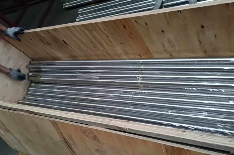
Seaworthy Wooden Cases & Pallets

Tailored Solutions, Timely Fulfillment

CUSTOMIZATION
& DELIVERY

Flexible Custom Manufacturing

We tailor stainless steel low-fin tube by outer diameter, wall thickness, fin height, fin density, requested length, material grade, and seamless or welded tube construction.

Low MOQ & Rapid Prototyping

Unlike high-volume state mills requiring 3–10 tonne minimums, TeCarve supports 100–300 kg flexible trial orders for standard and custom A498-type low-fin tubing, enabling rapid thermal testing, pilot runs, and emergency condenser re-tubing. Explore our partner factories' production lines via Verify Our Partner Factories.

Optimized Lead Time

In-stock standard sizes ship within 7–10 days. Custom specifications typically ship within 10–25 days after deposit, depending on order volume, dimensions, and surface finish. The full cycle—from inquiry and drawing confirmation through sampling, production, inspection, and dispatch—typically takes 33–55 days for custom items.

Global Logistics & On-Time Delivery

For low-fin tube exports worldwide, seaworthy wooden cases and pallets protect fin geometry, supported by anti-corrosion and moisture protection for long-distance transit.

How your order is made, checked and shipped

1 Forming stands on a welded stainless tube mill

Tube forming at the partner factory

2 Annealing furnace at operating temperature

Heat treatment (annealing)

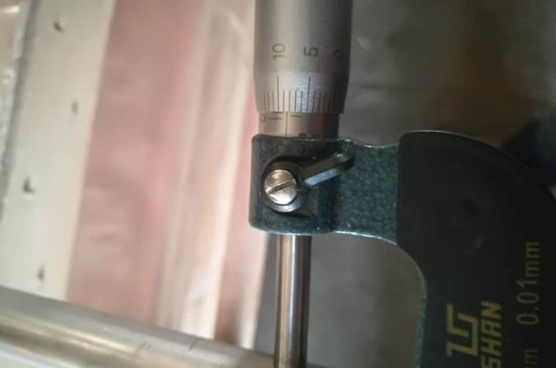
3 Caliper measuring polished tube outside diameter

Dimensional inspection

4 Handheld alloy analyzer screen showing a chemical composition result

Alloy verification with a handheld analyzer

5 Tubes in kraft paper with blue end caps in a lined case

Export packing

6 Tube bundles in woven bags loaded in a container

Container loading

Customer Trust & Verification

What Overseas Buyers Say About TeCarve Tubing

“I've received the goods and everything is fine.”

— Tommy, Nigeria
Batch delivery verified

“The goods already send to customers. I am waiting for the next order from them.”

— Khalid, Indonesia
Distributor reorder verified

“…there is no need of inspection this time… I trust in your product.”

— Carmen, Chile
Quality trust / inspection waiver verified

Frequently Asked Questions

What is a low fin tube and how does it improve heat exchanger performance?

A low fin tube is an integral heat exchanger tube with external helical fins cold-formed directly from the parent tube wall without an interfacial thermal gap, increasing external surface area by 2.5–3.5× (up to ~3.8× for high-density fins) versus plain tube of the same outer diameter. Because the fin outer diameter does not exceed the plain tube diameter, it is dimensioned to pass through TEMA standard baffle holes, reducing shell-side thermal resistance and boosting heat exchanger duty by 40–60% or enabling 30–50% more compact condenser bundles.

What fin specifications does TeCarve supply?

TeCarve supplies stainless steel integral low fin tubes (A498-type fin geometry) in base outer diameters from 12.7 mm (1/2 in) to 38.1 mm (1-1/2 in), with wall thicknesses from 0.8 mm to 2.5 mm. Standard fin densities include 19 FPI (1.34 mm pitch, ideal for fouling-prone fluids), 26 FPI (0.98 mm pitch, standard for HVAC/R chillers), 28 FPI, and 32 FPI (0.79 mm pitch, for high-vacuum clean condensing), with fin heights from 0.8 mm to 1.45 mm. Custom fin geometry, intermediate baffle lands, and unfinned end lengths are manufactured to engineering drawings.

What grades of stainless steel are available for low fin tubes?

Low fin tubes are available in austenitic grades 304, 304L, 316, 316L, 321, and duplex stainless steel 2205 (UNS S31803 / S32205). Grade 316L is preferred for chemical process condensers, acid gas coolers, and marine heat exchangers, while Duplex 2205 provides exceptional resistance to chloride stress corrosion cracking (SCC) and pitting in high-temperature brines.

What standards apply to stainless steel low fin tubes?

TeCarve stainless steel low fin tubes are made from base tubes conforming to ASTM A213 (seamless) or ASTM A249 (welded). Fin geometry, dimensional inspection and pneumatic testing follow ASTM A498 / A498M practice; A498 itself formally covers carbon steel base tubes (A179, A214, A334), so fin configuration is agreed per order. International specifications include EN 10216-5, DIN 28178, JIS G3463, and GB/T 24593. Every production lot undergoes 100% hydrostatic and eddy current non-destructive testing, dimensional checks, and is supplied with a fully traceable EN 10204 3.1 Mill Test Certificate.

When should I choose low fin tube over plain tube in a heat exchanger?

Low fin tube is preferred when the heat transfer coefficient on the shell-side (e.g., condensing refrigerant, condensing steam, viscous hydrocarbon, or gas cooling) is significantly lower than on the tube-side (e.g., cooling water). By expanding the external area by 2.5–3.5×, the controlling shell-side resistance is dramatically lowered. Furthermore, because integral low fin tubes have outer fin diameters no larger than the plain tube ends, existing shell-and-tube condensers can be directly retubed during maintenance turnarounds to increase throughput without modifying the shell, tubesheets, or piping connections.

How do you prevent wall thinning and bursting under the fin root?

Base tube wall thickness under fin grooves is inspected during rolling at our partner factories. Ordered minimum wall is kept within +18%/-0% and average wall within ±9% following A498-type practice, backed by 100% hydrostatic and eddy-current testing.

What custom plain end lengths and intermediate unfinned sections are available?

We provide custom unfinned plain end lengths (land sections) and intermediate unfinned sections fabricated to your equipment drawings on base tube ODs from 12.7 to 38.1 mm.

Contact TeCarve

Get in touch with TeCarve for premium stainless steel tubing solutions. Global delivery, factory-direct supply from two partner factories, and reliable service. If any need, please send email to sales@tecarve.com.