


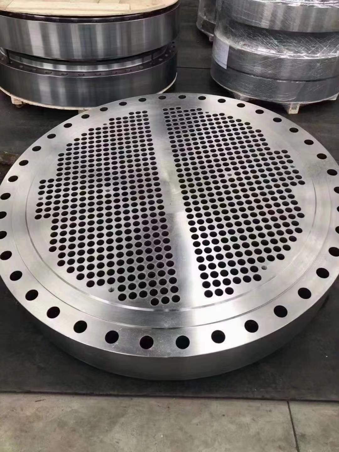
A tube sheet (tubesheet) is the thick drilled plate that holds the tubes of a shell-and-tube heat exchanger and separates the shell side from the tube side. GB/T 151-2026 sets a 25.20 mm hole for a 25 mm tube in Class T I, with a preferred pitch of at least 1.25 times the tube OD. TEMA sets the same 1.25 minimum.
Values are from GB/T 151-2026 clauses 7.3 to 7.6 and the TEMA Standards, 2007 edition, Section 5, clauses R/C/B-2.5 and RCB-7. Later TEMA editions exist, so check the edition your specification names.
Tube sheet hole size: GB/T 151-2026
GB/T 151 grades steel tube bundles as Class T I, I and II. These are the hole diameters for steel bundles from Tables 7-12, 7-13 and 7-14. The tolerance is the same in all three classes.
| Tube OD, mm | Class T I hole, mm | Class I hole, mm | Class II hole, mm | Hole tolerance, mm |
|---|---|---|---|---|
| 14 | 14.20 | 14.25 | 14.30 | +0.05 / −0.10 |
| 16 | 16.20 | 16.25 | 16.30 | +0.05 / −0.10 |
| 19 | 19.20 | 19.25 | 19.30 | +0.10 / −0.10 |
| 25 | 25.20 | 25.25 | 25.30 | +0.10 / −0.10 |
| 30 | 30.30 | 30.35 | 30.40 | +0.10 / −0.15 |
| 32 | 32.30 | 32.35 | 32.45 | +0.10 / −0.15 |
| 35 | 35.35 | 35.40 | 35.45 | +0.10 / −0.15 |
| 38 | 38.40 | 38.45 | 38.50 | +0.10 / −0.20 |
| 45 | 45.45 | 45.50 | 45.55 | +0.10 / −0.20 |
| 50 | 50.50 | 50.55 | 50.60 | +0.10 / −0.20 |
| 55 | 55.60 | 55.65 | 55.70 | +0.15 / −0.25 |
| 57 | 57.60 | 57.65 | 57.70 | +0.15 / −0.25 |
Clause 7.5.1.8 prefers Class T I holes for strength-expanded austenitic stainless, duplex, copper, titanium and nickel alloy tube ends, and for ungrooved strength expansion with helium leak testing. Other materials have their own tables.
Tube OD tolerance is graded the same way (Table 7-6, steel and nickel alloy tubes):
| Tube OD, mm | ≤ 25 | > 25 to 38 | > 38 to 50 | > 50 to 65 |
|---|---|---|---|---|
| Class T I | ±0.05 | ±0.10 | ±0.15 | ±0.20 |
| Class I | ±0.08 | ±0.13 | ±0.15 | ±0.20 |
| Class II | ±0.10 | ±0.15 | ±0.20 | ±0.25 |
Tube sheet hole size: TEMA
TEMA Table RCB-7.21M gives a standard fit and a special close fit. For the upper limit, 96 % of holes must meet column (c), and the rest may not exceed column (d).
| Tube OD, mm | Standard fit hole, mm | Under tolerance, mm | Close fit hole, mm | Under tolerance, mm | Over tolerance (c), mm | Over tolerance (d), mm |
|---|---|---|---|---|---|---|
| 6.4 | 6.58 | 0.10 | 6.53 | 0.05 | 0.05 | 0.18 |
| 9.5 | 9.75 | 0.10 | 9.70 | 0.05 | 0.05 | 0.18 |
| 12.7 | 12.95 | 0.10 | 12.90 | 0.05 | 0.05 | 0.20 |
| 15.9 | 16.13 | 0.10 | 16.08 | 0.05 | 0.05 | 0.25 |
| 19.1 | 19.30 | 0.10 | 19.25 | 0.05 | 0.05 | 0.25 |
| 22.2 | 22.48 | 0.10 | 22.43 | 0.05 | 0.05 | 0.25 |
| 25.4 | 25.70 | 0.10 | 25.65 | 0.05 | 0.05 | 0.25 |
| 31.8 | 32.11 | 0.15 | 32.03 | 0.08 | 0.08 | 0.25 |
| 38.1 | 38.56 | 0.18 | 38.46 | 0.08 | 0.08 | 0.25 |
| 50.8 | 51.36 | 0.18 | 51.26 | 0.08 | 0.08 | 0.25 |
| 63.5 | 64.20 | 0.25 | 64.07 | 0.10 | 0.10 | 0.25 |
| 76.2 | 77.04 | 0.30 | 76.89 | 0.11 | 0.10 | 0.25 |
TEMA also requires the inside edges of tube holes to be free of burrs, so they do not cut the tubes.
Tube pitch and layout
Pitch is the center-to-center distance between tubes. GB/T 151 lists four layouts: triangular (30°), rotated triangular (60°), square (90°) and rotated square (45°).
- Minimum pitch: 1.25 × tube OD in GB/T 151 (a preferred minimum) and TEMA. TEMA class C allows 1.20 × OD for tubes up to 15.9 mm with expanded-only joints.
- Mechanical cleaning, GB/T 151: use a square or rotated square layout with continuous straight lanes and a preferred clear gap of at least 6 mm. Pitch must be at least 17, 19 and 21 mm for 10, 12 and 14 mm tubes.
- Mechanical cleaning, TEMA: no triangular layouts when the shell side is cleaned mechanically. Class R and B lanes are at least 6.4 mm, or 4.8 mm in class B shells up to 305 mm.
Common pitches from GB/T 151 Table 7-2:
| Tube OD d, mm | Pitch S, mm | Pitch across pass partition Sn, mm |
|---|---|---|
| 10 | 13–14 | 28 |
| 12 | 16 | 30 |
| 14 | 19 | 32 |
| 16 | 22 | 35 |
| 19 | 25 | 38 |
| 20 | 26 | 40 |
| 22 | 28 | 42 |
| 25 | 32 | 44 |
| 30 | 38 | 50 |
| 32 | 40 | 52 |
| 35 | 44 | 56 |
| 38 | 48 | 60 |
| 45 | 57 | 68 |
| 50 | 64 | 76 |
| 55 | 70 | 78 |
| 57 | 72 | 80 |
Tube sheet thickness
Thickness comes from a design calculation, not a size table. Use GB/T 151 clause 8.4, TEMA Appendix A, or ASME Section VIII Division 1 Part UHX, as your code requires. TEMA adds these minimums for expanded joints (R/C/B-7.11):
| TEMA class | Minimum in the expanded area, less corrosion allowance | Minimum total, with corrosion allowance |
|---|---|---|
| R | Tube OD | 19.1 mm (3/4 in) |
| C | 3/4 of tube OD up to 25.4 mm tube; 22.2 mm for 31.8 mm tube; 25.4 mm for 38.1 mm tube; 31.8 mm for 50.8 mm tube | Not stated |
| B | Same as class C | 19.1 mm (3/4 in) |
Tube-to-tubesheet joints
| Joint | GB/T 151-2026 recommends it for | Key limits |
|---|---|---|
| Strength expansion | Design pressure up to 5.0 MPa and design temperature up to 300 °C, with no vibration, large temperature swings or marked stress corrosion tendency | Pull-out test to Annex I. Expanded length: the smaller of tubesheet thickness − 3 mm (− 5 mm for flexible expansion) and 50 mm |
| Seal expansion | Closing the crevice, used beyond the strength expansion length or with a strength weld | Expansion degree of 1–3 % |
| Strength weld | Titanium tubes; austenitic tubes in non-alloy or low-alloy steel tubesheets above 200 °C; no crevice corrosion tendency; no vibration or cyclic load; temperature excursion service | Weld dimension l at least equal to the tube wall |
| Seal weld | Normally a fillet, with leg height set by the design documents | Not a strength joint |
| Expansion and weld | Vibration or cyclic load, crevice corrosion tendency, clad tubesheets | Welded first: expansion stays at least 8 mm from the weld root, except for flexible and stayed tubesheets |
Expansion degree from GB/T 151 Table 7-26 can be adjusted from pull-out test results. In wet H2S stress corrosion service, the recommended degree is 2 % or less for duplex tubes and flexible expansion. The flexible figures do not apply to duplex tubes in non-duplex tubesheets.
| Tube material | Mechanical expansion, % | Flexible expansion, % |
|---|---|---|
| Ferritic or austenitic stainless | 5–8 | 1–4 |
| Austenitic-ferritic duplex | 2–4 | 1–4 |
| Non-alloy and low-alloy steel | 5–8 | 1–4 |
| Chromium-molybdenum steel | 5–8 | 1–4 |
| Titanium and alloys | 5–8 | 1–4 |
| Nickel and alloys | 4–6 | 1–4 |
| Zirconium and alloys | 2–5 | 1–4 |
Grooves and tube projection
| Item | GB/T 151-2026 | TEMA (2007) |
|---|---|---|
| Two grooves when | Tubesheet over 38 mm and tube OD over 14 mm, mechanical expansion | Tubesheet over 25.4 mm, roller expansion (classes R and B); over 76 mm, hydraulic or explosive |
| One groove allowed | Tubesheet up to 38 mm | Tubesheet up to 25.4 mm, or up to 76 mm for hydraulic or explosive |
| Groove size | 0.5 mm deep for tube OD 16–57 mm; may be omitted up to 14 mm | About 3.2 mm wide by 0.4 mm deep for roller expansion |
| Clad tubesheets | Prefer grooves in the base metal | Grooves in the base metal unless the purchaser specifies otherwise |
| Tube projection | Preferably no more than 5 mm beyond the face, unless the design documents differ | Flush, or no more than half a tube diameter; flush at the top tubesheet of vertical exchangers unless specified otherwise |
Strength-welded joints do not need ring grooves under TEMA RB-7.24.
Pass partition grooves
GB/T 151 clause 7.5.3.2 sets the groove deeper than the gasket and preferably at least 4 mm deep, with a preferred width of 8–14 mm. The groove sealing face should be level with the ring sealing face.
Ordering a tube sheet
TeCarve exports tube sheets and baffle plates sourced from qualified specialist makers and inspected by TeCarve. They are machined to the exchanger drawing: OD 150–2500 mm, thickness 15–200 mm, in F304L or F316L forgings, or 16Mn III low-alloy steel with explosion-clad 316L. They start at 1 piece, and lead time is about 20–30 days, including CNC deep-hole drilling and ultrasonic checks of ligament thickness.
- Send: the drawing, with OD, thickness, hole size and tolerance, pitch and layout.
- State: the code and edition, material and any cladding, grooves, partition grooves, and the tests you need.
Where a bundle needs more surface area, see our stainless steel low fin tube. Tubes for the bundle are covered in our ASTM A249 heat exchanger tube guide and stainless steel tube size chart. More references are in our technical resources.
Frequently asked questions
What is a tube sheet?
It is the thick drilled plate that holds the tubes of a shell-and-tube heat exchanger. It seals the shell side from the tube side, and each tube is expanded or welded into its hole.
What size is a tube sheet hole?
It depends on the tube OD and class. GB/T 151-2026 gives 25.20, 25.25 and 25.30 mm for a 25 mm tube in Classes T I, I and II. TEMA gives 25.70 mm standard fit and 25.65 mm close fit for a 25.4 mm tube.
What is the minimum tube pitch?
TEMA sets 1.25 times the tube OD, and GB/T 151-2026 uses the same figure as a preferred minimum. TEMA class C allows 1.20 times OD for tubes up to 15.9 mm with expanded-only joints.
How thick should a tube sheet be?
Thickness comes from a design calculation under GB/T 151 clause 8.4, TEMA Appendix A or ASME VIII-1 Part UHX. TEMA also sets minimums: for class R expanded joints, at least the tube OD after corrosion allowance and 19.1 mm in total.
When is a tube-to-tubesheet joint welded instead of expanded?
GB/T 151-2026 limits strength expansion to 5.0 MPa and 300 °C without vibration. It recommends strength welds for titanium tubes, and for austenitic tubes in non-alloy or low-alloy steel tubesheets above 200 °C. Expansion and welding together suit vibration, crevice corrosion and clad tubesheets.