

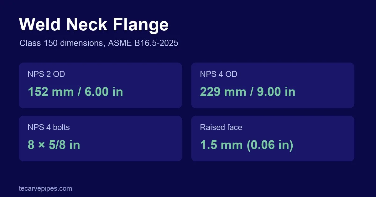

A weld neck flange (welding neck flange) has a long tapered hub that is butt-welded to the pipe. The taper spreads stress from the pipe into the flange, and the butt weld can be fully radiographed, so weld neck flanges are the usual choice for high pressure, high or cyclic temperature and critical service. In the US system they are dimensioned by ASME B16.5 (NPS 1/2 to 24) and B16.47 (NPS 26 to 60).
Dimensions are from ASME B16.5-2025: Table 8 (Class 150 flanges, SI units), Table 8C (U.S. customary units) and Table 7 (drilling templates, Class 150). Other pressure classes have their own tables in the standard.
Weld neck vs slip-on and other flange types
| Type | How it attaches | Typical use |
|---|---|---|
| Weld neck | Butt weld at the end of a tapered hub | High pressure and temperature, cyclic loads, lines that need full radiography |
| Slip-on | Pipe slides into the flange; fillet welds inside and outside | Lower-pressure service where easier alignment is wanted |
| Socket weld | Pipe sits in a socket; fillet weld outside (B16.5 lists NPS 1/2 to 3) | Small-bore lines |
| Threaded | Screwed onto threaded pipe | Small-bore, non-welded service |
| Lap joint | Loose flange behind a stub end | Frequent dismantling; costly alloy kept to the stub end |
| Blind | Closes the end of a line | Ends, test points, future connections |
Class 150 weld neck flange dimensions, mm (ASME B16.5-2025)
O, tf, X, Ah, Y and B from Table 8; bolt circle, number and size of bolts from Table 7. Bolt hole and bolt diameters are in inches, as in the standard. * Bore for NPS 14 and larger is specified by the purchaser.
| NPS | Flange OD O | Thickness tf min | Hub dia X | Hub dia at bevel Ah | Length through hub Y | Bore B | Bolt circle W | Bolts | Bolt hole, in. | Bolt, in. |
|---|---|---|---|---|---|---|---|---|---|---|
| 1/2 | 89 | 9.7 | 30 | 21.3 | 46 | 15.7 | 60.5 | 5/8 | 4 | 1/2 |
| 3/4 | 99 | 11.2 | 38 | 26.7 | 51 | 20.8 | 69.8 | 5/8 | 4 | 1/2 |
| 1 | 108 | 12.7 | 49 | 33.5 | 54 | 26.7 | 79.2 | 5/8 | 4 | 1/2 |
| 1 1/4 | 117 | 14.2 | 59 | 42.2 | 56 | 35.1 | 88.9 | 5/8 | 4 | 1/2 |
| 1 1/2 | 127 | 15.9 | 65 | 48.3 | 60 | 40.9 | 98.6 | 5/8 | 4 | 1/2 |
| 2 | 152 | 17.5 | 78 | 60.5 | 62 | 52.6 | 120.6 | 3/4 | 4 | 5/8 |
| 2 1/2 | 178 | 20.6 | 90 | 73.2 | 68 | 62.7 | 139.7 | 3/4 | 4 | 5/8 |
| 3 | 190 | 22.4 | 108 | 88.9 | 68 | 78.0 | 152.4 | 3/4 | 4 | 5/8 |
| 3 1/2 | 216 | 22.4 | 122 | 101.6 | 70 | 90.2 | 177.8 | 3/4 | 8 | 5/8 |
| 4 | 229 | 22.4 | 135 | 114.3 | 75 | 102.4 | 190.5 | 3/4 | 8 | 5/8 |
| 5 | 254 | 22.4 | 164 | 141.2 | 87 | 128.3 | 215.9 | 7/8 | 8 | 3/4 |
| 6 | 279 | 23.9 | 192 | 168.4 | 87 | 154.2 | 241.3 | 7/8 | 8 | 3/4 |
| 8 | 343 | 26.9 | 246 | 219.2 | 100 | 202.7 | 298.4 | 7/8 | 8 | 3/4 |
| 10 | 406 | 28.4 | 305 | 273.0 | 100 | 254.5 | 362.0 | 1 | 12 | 7/8 |
| 12 | 483 | 30.2 | 365 | 323.8 | 113 | 304.8 | 431.8 | 1 | 12 | 7/8 |
| 14 | 533 | 33.3 | 400 | 355.6 | 125 | * | 476.2 | 1 1/8 | 12 | 1 |
| 16 | 597 | 35.1 | 457 | 406.4 | 125 | * | 539.8 | 1 1/8 | 16 | 1 |
| 18 | 635 | 38.1 | 505 | 457.2 | 138 | * | 577.8 | 1 1/4 | 16 | 1 1/8 |
| 20 | 698 | 41.1 | 559 | 508.0 | 143 | * | 635.0 | 1 1/4 | 20 | 1 1/8 |
| 22 | 749 | 44.4 | 610 | 558.8 | 148 | * | 692.2 | 1 3/8 | 20 | 1 1/4 |
| 24 | 813 | 46.0 | 663 | 609.6 | 151 | * | 749.3 | 1 3/8 | 20 | 1 1/4 |
Class 150 weld neck flange dimensions, inches (Table 8C)
| NPS | O | tf min | X | Ah | Y | B |
|---|---|---|---|---|---|---|
| 1/2 | 3.50 | 0.38 | 1.19 | 0.84 | 1.81 | 0.62 |
| 3/4 | 3.88 | 0.44 | 1.50 | 1.05 | 2.00 | 0.82 |
| 1 | 4.25 | 0.50 | 1.94 | 1.32 | 2.12 | 1.05 |
| 1 1/4 | 4.62 | 0.56 | 2.31 | 1.66 | 2.19 | 1.38 |
| 1 1/2 | 5.00 | 0.62 | 2.56 | 1.90 | 2.38 | 1.61 |
| 2 | 6.00 | 0.69 | 3.06 | 2.38 | 2.44 | 2.07 |
| 2 1/2 | 7.00 | 0.81 | 3.56 | 2.88 | 2.69 | 2.47 |
| 3 | 7.50 | 0.88 | 4.25 | 3.50 | 2.69 | 3.07 |
| 3 1/2 | 8.50 | 0.88 | 4.81 | 4.00 | 2.75 | 3.55 |
| 4 | 9.00 | 0.88 | 5.31 | 4.50 | 2.94 | 4.03 |
| 5 | 10.00 | 0.88 | 6.44 | 5.56 | 3.44 | 5.05 |
| 6 | 11.00 | 0.94 | 7.56 | 6.63 | 3.44 | 6.07 |
| 8 | 13.50 | 1.06 | 9.69 | 8.63 | 3.94 | 7.98 |
| 10 | 16.00 | 1.12 | 12.00 | 10.75 | 3.94 | 10.02 |
| 12 | 19.00 | 1.19 | 14.38 | 12.75 | 4.44 | 12.00 |
| 14 | 21.00 | 1.31 | 15.75 | 14.00 | 4.94 | * |
| 16 | 23.50 | 1.38 | 18.00 | 16.00 | 4.94 | * |
| 18 | 25.00 | 1.50 | 19.88 | 18.00 | 5.44 | * |
| 20 | 27.50 | 1.62 | 22.00 | 20.00 | 5.62 | * |
| 22 | 29.50 | 1.75 | 24.00 | 22.00 | 5.82 | * |
| 24 | 32.00 | 1.81 | 26.12 | 24.00 | 5.94 | * |
Notes from the standard
- Dimensions shown are for the regularly furnished 1.5 mm (0.06 in.) raised face, except lapped flanges.
- The welding neck bore B corresponds to the inside diameter of standard-wall pipe in ASME B36.10M (the same as Schedule 40 for NPS 10 and smaller) and is furnished unless the purchaser specifies otherwise. For NPS 14 and larger the purchaser specifies the bore.
- The minimum hub height H is 2(Y − tf)/3.
- Where a flat face is required, it may be the full tf plus 1.5 mm (0.06 in.), or tf without the raised face height.
- For reducing weld neck flanges, see B16.5 para. 6.8; for bevels, para. 6.7.
How to order a stainless steel weld neck flange
- Size (NPS) and pressure class, for example NPS 4 Class 150.
- Facing: raised face (RF), flat face (FF) or ring-type joint (RTJ).
- Bore: the pipe schedule the neck will be welded to, for example Sch 40S or 10S. The bore must match the pipe ID.
- Material: ASTM A182 F304/F304L, F316/F316L or duplex F51/F53.
- Standard: ASME B16.5 (NPS 1/2–24) or B16.47 Series A/B (NPS 26–60); EN 1092-1 for PN flanges.
- Certificate: EN 10204 3.1 with heat number on the flange.
See the stainless steel pipe fittings and flanges page for the flanges TeCarve supplies, sourced from qualified specialist makers and inspected before export. Related: concentric vs eccentric reducers, pipe schedule chart, technical resources.
Frequently asked questions
What is a weld neck flange?
A flange with a long tapered hub that is butt-welded to the pipe. It is used for high pressure, high or cyclic temperature and critical service.
What are the dimensions of a 4 inch Class 150 weld neck flange?
ASME B16.5-2025 gives OD 229 mm (9.00 in.), minimum thickness 22.4 mm (0.88 in.), length through hub 75 mm (2.94 in.), bolt circle 190.5 mm, and eight 5/8 in. bolts in 3/4 in. holes.
What is the difference between a weld neck and a slip-on flange?
A weld neck flange is butt-welded at the end of a tapered hub; a slip-on flange slides over the pipe and is fillet-welded. Weld neck flanges suit higher pressure and cyclic service.
Does the weld neck bore have to match the pipe?
Yes. B16.5 furnishes a bore equal to the ID of standard-wall pipe unless the purchaser specifies otherwise, and for NPS 14 and larger the purchaser must specify it.