

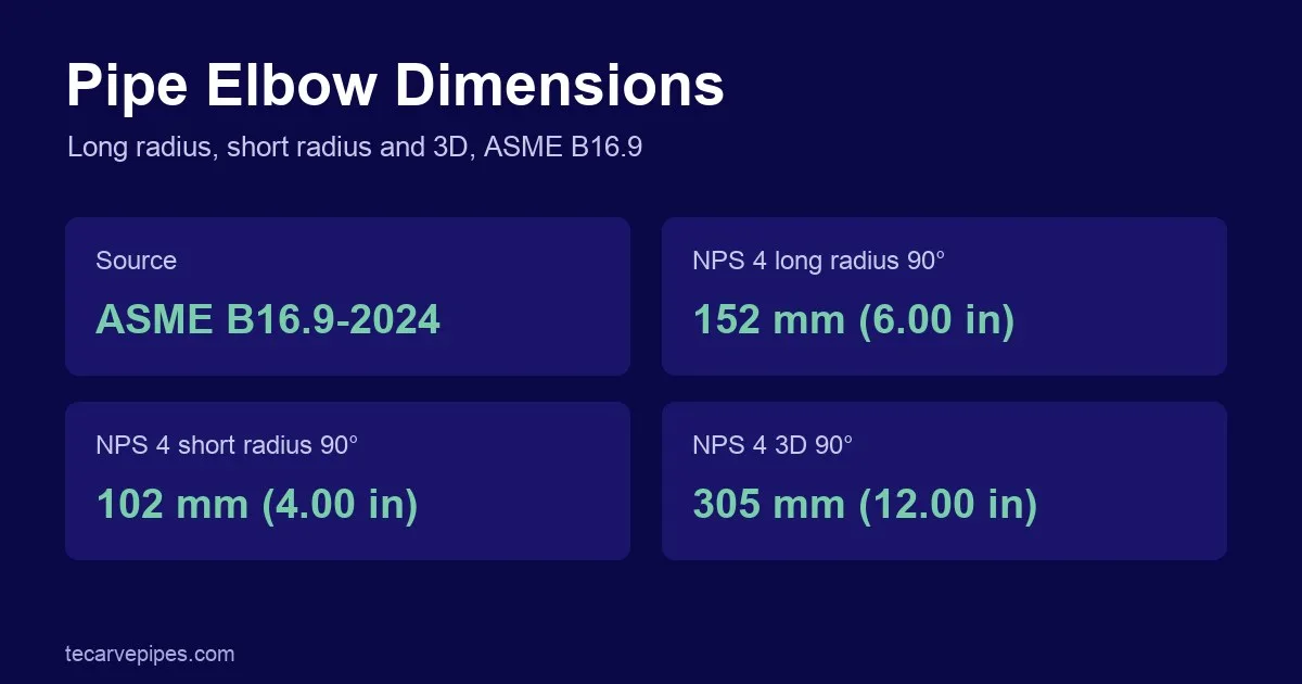

Butt-weld pipe elbow dimensions are set by ASME B16.9 as a center-to-end distance from the fitting centerline to each welding end. A long radius 90° elbow in NPS 4 is 152 mm (6.00 in) center-to-end, a short radius one is 102 mm (4.00 in) and a 3D elbow is 305 mm (12.00 in). The charts below give every size.
Dimensions are from ASME B16.9-2024 Tables 6.1-1 to 6.1-6 and Table 11.2-1, and the metric series from GB/T 12459-2017 Table 2. Values are in millimetres with inches in brackets, as printed in the standard.
Long radius vs short radius vs 3D elbows
The three elbow types differ in centerline radius, which sets the center-to-end length A. In the B16.9 tables, A for a 90° elbow follows a simple pattern:
| Elbow type | Centerline radius | 90° center-to-end A | B16.9 sizes | Example, NPS 4 |
|---|---|---|---|---|
| Long radius (LR) | 1.5 × NPS | 1.5 × NPS in inches, from NPS 1 | NPS ½ to 48 | 152 mm (6.00 in) |
| Short radius (SR) | 1 × NPS | NPS in inches | NPS 1 to 24 | 102 mm (4.00 in) |
| 3D radius | 3 × NPS | 3 × NPS in inches | NPS ¾ to 48 | 305 mm (12.00 in) |
Long radius is the default choice because the gentler turn gives a lower pressure drop and less erosion. Short radius elbows save space where the run is tight. 3D elbows suit slurry, pigging and high-velocity lines where an even gentler bend is needed. NPS ½ and ¾ long radius elbows are an exception to the 1.5 × NPS rule: both are 38 mm (1.50 in).
Long radius elbow dimensions: 90° and 45°
ASME B16.9-2024 Table 6.1-1. A is the 90° center-to-end and B is the 45° center-to-end, both measured from the centerline intersection to the welding end.
| NPS | OD at bevel, mm (in) | 90° elbow A, mm (in) | 45° elbow B, mm (in) |
|---|---|---|---|
| ½ | 21.3 (0.84) | 38 (1.50) | 16 (0.62) |
| ¾ | 26.7 (1.05) | 38 (1.50) | 19 (0.75) |
| 1 | 33.4 (1.32) | 38 (1.50) | 22 (0.88) |
| 1¼ | 42.2 (1.66) | 48 (1.88) | 25 (1.00) |
| 1½ | 48.3 (1.90) | 57 (2.25) | 29 (1.12) |
| 2 | 60.3 (2.38) | 76 (3.00) | 35 (1.38) |
| 2½ | 73.0 (2.88) | 95 (3.75) | 44 (1.75) |
| 3 | 88.9 (3.50) | 114 (4.50) | 51 (2.00) |
| 3½ | 101.6 (4.00) | 133 (5.25) | 57 (2.25) |
| 4 | 114.3 (4.50) | 152 (6.00) | 64 (2.50) |
| 5 | 141.3 (5.56) | 190 (7.50) | 79 (3.12) |
| 6 | 168.3 (6.62) | 229 (9.00) | 95 (3.75) |
| 8 | 219.1 (8.62) | 305 (12.00) | 127 (5.00) |
| 10 | 273.0 (10.75) | 381 (15.00) | 159 (6.25) |
| 12 | 323.8 (12.75) | 457 (18.00) | 190 (7.50) |
| 14 | 355.6 (14.00) | 533 (21.00) | 222 (8.75) |
| 16 | 406.4 (16.00) | 610 (24.00) | 254 (10.00) |
| 18 | 457.0 (18.00) | 686 (27.00) | 286 (11.25) |
| 20 | 508.0 (20.00) | 762 (30.00) | 318 (12.50) |
| 22 | 559.0 (22.00) | 838 (33.00) | 343 (13.50) |
| 24 | 610.0 (24.00) | 914 (36.00) | 381 (15.00) |
| 26 | 660.0 (26.00) | 991 (39.00) | 406 (16.00) |
| 28 | 711.0 (28.00) | 1067 (42.00) | 438 (17.25) |
| 30 | 762.0 (30.00) | 1143 (45.00) | 470 (18.50) |
| 32 | 813.0 (32.00) | 1219 (48.00) | 502 (19.75) |
| 34 | 864.0 (34.00) | 1295 (51.00) | 533 (21.00) |
| 36 | 914.0 (36.00) | 1372 (54.00) | 565 (22.25) |
| 38 | 965.0 (38.00) | 1448 (57.00) | 600 (23.62) |
| 40 | 1016.0 (40.00) | 1524 (60.00) | 632 (24.88) |
| 42 | 1067.0 (42.00) | 1600 (63.00) | 660 (26.00) |
| 44 | 1118.0 (44.00) | 1676 (66.00) | 695 (27.38) |
| 46 | 1168.0 (46.00) | 1753 (69.00) | 727 (28.62) |
| 48 | 1219.0 (48.00) | 1829 (72.00) | 759 (29.88) |
Long radius reducing elbows (Table 6.1-2, NPS 2 × 1 to 24 × 12) keep the A dimension of the large-end size, so a 4 × 3 reducing elbow is also 152 mm (6.00 in).
Short radius elbow dimensions: 90°
ASME B16.9-2024 Table 6.1-4. Short radius elbows are listed from NPS 1 to 24 and only as 90° elbows.
| NPS | OD at bevel, mm (in) | 90° elbow A, mm (in) |
|---|---|---|
| 1 | 33.4 (1.32) | 25 (1.00) |
| 1¼ | 42.2 (1.66) | 32 (1.25) |
| 1½ | 48.3 (1.90) | 38 (1.50) |
| 2 | 60.3 (2.38) | 51 (2.00) |
| 2½ | 73.0 (2.88) | 64 (2.50) |
| 3 | 88.9 (3.50) | 76 (3.00) |
| 3½ | 101.6 (4.00) | 89 (3.50) |
| 4 | 114.3 (4.50) | 102 (4.00) |
| 5 | 141.3 (5.56) | 127 (5.00) |
| 6 | 168.3 (6.62) | 152 (6.00) |
| 8 | 219.1 (8.62) | 203 (8.00) |
| 10 | 273.0 (10.75) | 254 (10.00) |
| 12 | 323.8 (12.75) | 305 (12.00) |
| 14 | 355.6 (14.00) | 356 (14.00) |
| 16 | 406.4 (16.00) | 406 (16.00) |
| 18 | 457.0 (18.00) | 457 (18.00) |
| 20 | 508.0 (20.00) | 508 (20.00) |
| 22 | 559.0 (22.00) | 559 (22.00) |
| 24 | 610.0 (24.00) | 610 (24.00) |
3D elbow dimensions: 90° and 45°
ASME B16.9-2024 Table 6.1-6.
| NPS | OD at bevel, mm (in) | 90° elbow A, mm (in) | 45° elbow B, mm (in) |
|---|---|---|---|
| ¾ | 26.7 (1.05) | 57 (2.25) | 24 (0.94) |
| 1 | 33.4 (1.32) | 76 (3.00) | 31 (1.25) |
| 1¼ | 42.2 (1.66) | 95 (3.75) | 39 (1.56) |
| 1½ | 48.3 (1.90) | 114 (4.50) | 47 (1.88) |
| 2 | 60.3 (2.38) | 152 (6.00) | 63 (2.50) |
| 2½ | 73.0 (2.88) | 190 (7.50) | 79 (3.12) |
| 3 | 88.9 (3.50) | 229 (9.00) | 95 (3.75) |
| 3½ | 101.6 (4.00) | 267 (10.50) | 111 (4.38) |
| 4 | 114.3 (4.50) | 305 (12.00) | 127 (5.00) |
| 5 | 141.3 (5.56) | 381 (15.00) | 157 (6.19) |
| 6 | 168.3 (6.62) | 457 (18.00) | 189 (7.44) |
| 8 | 219.1 (8.62) | 610 (24.00) | 252 (9.94) |
| 10 | 273.0 (10.75) | 762 (30.00) | 316 (12.44) |
| 12 | 323.8 (12.75) | 914 (36.00) | 378 (14.88) |
| 14 | 355.6 (14.00) | 1067 (42.00) | 441 (17.38) |
| 16 | 406.4 (16.00) | 1219 (48.00) | 505 (19.88) |
| 18 | 457.0 (18.00) | 1372 (54.00) | 568 (22.38) |
| 20 | 508.0 (20.00) | 1524 (60.00) | 632 (24.88) |
| 22 | 559.0 (22.00) | 1676 (66.00) | 694 (27.31) |
| 24 | 610.0 (24.00) | 1829 (72.00) | 757 (29.81) |
| 26 | 660.0 (26.00) | 1981 (78.00) | 821 (32.31) |
| 28 | 711.0 (28.00) | 2134 (84.00) | 883 (34.75) |
| 30 | 762.0 (30.00) | 2286 (90.00) | 946 (37.25) |
| 32 | 813.0 (32.00) | 2438 (96.00) | 1010 (39.75) |
| 34 | 864.0 (34.00) | 2591 (102.00) | 1073 (42.25) |
| 36 | 914.0 (36.00) | 2743 (108.00) | 1135 (44.69) |
| 38 | 965.0 (38.00) | 2896 (114.00) | 1200 (47.25) |
| 40 | 1016.0 (40.00) | 3048 (120.00) | 1264 (49.75) |
| 42 | 1067.0 (42.00) | 3200 (126.00) | 1326 (52.19) |
| 44 | 1118.0 (44.00) | 3353 (132.00) | 1389 (54.69) |
| 46 | 1168.0 (46.00) | 3505 (138.00) | 1453 (57.19) |
| 48 | 1219.0 (48.00) | 3658 (144.00) | 1516 (59.69) |
180° return dimensions
For 180° returns, O is the center-to-center distance between the two legs and K is the back-to-face distance. A is half of O. Long radius returns are in Table 6.1-3 and short radius returns in Table 6.1-5.
Long radius 180° returns
| NPS | OD at bevel, mm (in) | Center-to-center O, mm (in) | Back-to-face K, mm (in) |
|---|---|---|---|
| ½ | 21.3 (0.84) | 76 (3.00) | 48 (1.88) |
| ¾ | 26.7 (1.05) | 76 (3.00) | 51 (2.00) |
| 1 | 33.4 (1.32) | 76 (3.00) | 56 (2.19) |
| 1¼ | 42.2 (1.66) | 95 (3.75) | 70 (2.75) |
| 1½ | 48.3 (1.90) | 114 (4.50) | 83 (3.25) |
| 2 | 60.3 (2.38) | 152 (6.00) | 106 (4.19) |
| 2½ | 73.0 (2.88) | 190 (7.50) | 132 (5.19) |
| 3 | 88.9 (3.50) | 229 (9.00) | 159 (6.25) |
| 3½ | 101.6 (4.00) | 267 (10.50) | 184 (7.25) |
| 4 | 114.3 (4.50) | 305 (12.00) | 210 (8.25) |
| 5 | 141.3 (5.56) | 381 (15.00) | 262 (10.31) |
| 6 | 168.3 (6.62) | 457 (18.00) | 313 (12.31) |
| 8 | 219.1 (8.62) | 610 (24.00) | 414 (16.31) |
| 10 | 273.0 (10.75) | 762 (30.00) | 518 (20.38) |
| 12 | 323.8 (12.75) | 914 (36.00) | 619 (24.38) |
| 14 | 355.6 (14.00) | 1067 (42.00) | 711 (28.00) |
| 16 | 406.4 (16.00) | 1219 (48.00) | 813 (32.00) |
| 18 | 457.0 (18.00) | 1372 (54.00) | 914 (36.00) |
| 20 | 508.0 (20.00) | 1524 (60.00) | 1016 (40.00) |
| 22 | 559.0 (22.00) | 1676 (66.00) | 1118 (44.00) |
| 24 | 610.0 (24.00) | 1829 (72.00) | 1219 (48.00) |
Short radius 180° returns
| NPS | OD at bevel, mm (in) | Center-to-center O, mm (in) | Back-to-face K, mm (in) |
|---|---|---|---|
| 1 | 33.4 (1.32) | 51 (2.00) | 41 (1.62) |
| 1¼ | 42.2 (1.66) | 64 (2.50) | 52 (2.06) |
| 1½ | 48.3 (1.90) | 76 (3.00) | 62 (2.44) |
| 2 | 60.3 (2.38) | 102 (4.00) | 81 (3.19) |
| 2½ | 73.0 (2.88) | 127 (5.00) | 100 (3.94) |
| 3 | 88.9 (3.50) | 152 (6.00) | 121 (4.75) |
| 3½ | 101.6 (4.00) | 178 (7.00) | 140 (5.50) |
| 4 | 114.3 (4.50) | 203 (8.00) | 159 (6.25) |
| 5 | 141.3 (5.56) | 254 (10.00) | 197 (7.75) |
| 6 | 168.3 (6.62) | 305 (12.00) | 237 (9.31) |
| 8 | 219.1 (8.62) | 406 (16.00) | 313 (12.31) |
| 10 | 273.0 (10.75) | 508 (20.00) | 391 (15.38) |
| 12 | 323.8 (12.75) | 610 (24.00) | 467 (18.38) |
| 14 | 355.6 (14.00) | 711 (28.00) | 533 (21.00) |
| 16 | 406.4 (16.00) | 813 (32.00) | 610 (24.00) |
| 18 | 457.0 (18.00) | 914 (36.00) | 686 (27.00) |
| 20 | 508.0 (20.00) | 1016 (40.00) | 762 (30.00) |
| 22 | 559.0 (22.00) | 1118 (44.00) | 838 (33.00) |
| 24 | 610.0 (24.00) | 1219 (48.00) | 914 (36.00) |
Elbows at other angles: segment formula
ASME B16.9-2024 para. 6.2.4 allows factory-made segments of long radius, short radius and 3D elbows to meet a customer angle. The center-to-end of the segment is:
Bs = A × tan(θ / 2)
A is the 90° center-to-end for the same radius type and size, and θ is the segment angle, such as 30°, 60° or 75°. For an NPS 4 long radius elbow cut to 60°, Bs = 152 × tan 30° ≈ 88 mm. With 45°, the formula gives 152 × tan 22.5° ≈ 63 mm, close to the 64 mm in Table 6.1-1. The standard also notes that once an elbow is cut in the field, the segment is no longer a B16.9 product.
Elbow dimensional tolerances
ASME B16.9-2024 Table 11.2-1, in mm with inches in brackets. Tolerances are equal plus and minus except where shown.
| NPS | OD at bevel, mm | Center-to-end, LR and SR elbows, mm (in) | Center-to-end, 3D elbows, mm (in) |
|---|---|---|---|
| ½ to 2½ | +1.6 / −0.8 | ±2 (0.06) | ±3 (0.09) |
| 3 to 3½ | ±1.6 | ±2 (0.06) | ±3 (0.09) |
| 4 | ±1.6 | ±2 (0.06) | ±3 (0.09) |
| 5 to 8 | +2.4 / −1.6 | ±2 (0.06) | ±3 (0.09) |
| 10 to 18 | +4.0 / −3.2 | ±2 (0.09) | ±3 (0.12) |
| 20 to 24 | +6.4 / −4.8 | ±2 (0.09) | ±3 (0.12) |
| 26 to 30 | +6.4 / −4.8 | ±3 (0.12) | ±6 (0.25) |
| 32 to 48 | +6.4 / −4.8 | ±5 (0.19) | ±6 (0.38) |
For 180° returns the center-to-center O tolerance is ±6 mm (0.25 in) up to NPS 8 and ±10 mm (0.38 in) for NPS 10 to 24, with back-to-face K at ±6 mm (0.25 in) up to NPS 24. Angularity limits are:
| NPS | Off angle Q, mm (in) | Off plane P, mm (in) |
|---|---|---|
| ½ to 4 | 1 (0.03) | 2 (0.06) |
| 5 to 8 | 2 (0.06) | 4 (0.12) |
| 10 to 12 | 3 (0.09) | 5 (0.19) |
| 14 to 16 | 3 (0.09) | 6 (0.25) |
| 18 to 24 | 4 (0.12) | 10 (0.38) |
| 26 to 30 | 5 (0.19) | 10 (0.38) |
| 32 to 42 | 5 (0.19) | 13 (0.50) |
| 44 to 48 | 5 (0.19) | 19 (0.75) |
Metric series: GB/T 12459-2017
GB/T 12459-2017 gives two outside diameter series. Series I is the general, recommended series; Series II is a non-general series used for metric pipe. The center-to-end dimensions in Table 2 are the same as ASME B16.9 for both series. Note that some Series I diameters differ slightly from B16.9, for example 26.9 mm instead of 26.7 mm for DN 20 and 323.9 mm instead of 323.8 mm for DN 300.
| DN | NPS | Series I OD, mm | Series II OD, mm | 90° elbow A, mm | 45° elbow B, mm |
|---|---|---|---|---|---|
| 15 | 1/2 | 21.3 | 18 | 38 | 16 |
| 20 | 3/4 | 26.9 | 25 | 38 | 19 |
| 25 | 1 | 33.7 | 32 | 38 | 22 |
| 32 | 1¼ | 42.4 | 38 | 48 | 25 |
| 40 | 1½ | 48.3 | 45 | 57 | 29 |
| 50 | 2 | 60.3 | 57 | 76 | 35 |
| 65 | 2½ | 73.0 | 76 | 95 | 44 |
| 80 | 3 | 88.9 | 89 | 114 | 51 |
| 90 | 3½ | 101.6 | — | 133 | 57 |
| 100 | 4 | 114.3 | 108 | 152 | 64 |
| 125 | 5 | 141.3 | 133 | 190 | 79 |
| 150 | 6 | 168.3 | 159 | 229 | 95 |
| 200 | 8 | 219.1 | 219 | 305 | 127 |
| 250 | 10 | 273.0 | 273 | 381 | 159 |
| 300 | 12 | 323.9 | 325 | 457 | 190 |
| 350 | 14 | 355.6 | 377 | 533 | 222 |
| 400 | 16 | 406.4 | 426 | 610 | 254 |
| 450 | 18 | 457 | 480 | 686 | 286 |
| 500 | 20 | 508 | 530 | 762 | 318 |
| 550 | 22 | 559 | — | 838 | 343 |
| 600 | 24 | 610 | 630 | 914 | 381 |
What to specify when ordering an elbow
- Type and angle: long radius, short radius or 3D, and 90°, 45° or 180°.
- Size and wall: NPS or DN and the schedule or wall thickness, which must match the pipe.
- Standard and material: for example ASME B16.9 in ASTM A403 WP316L, or GB/T 12459.
- Seamless or welded: and any NDT or certificate requirement, such as EN 10204 3.1.
- End preparation: welding bevel per ASME B16.9 Table 8-1 unless a drawing specifies otherwise.
TeCarve supplies stainless steel butt-weld elbows to ASME B16.9 from NPS ½ to 48 in ASTM A403 grades. They are sourced from qualified specialist makers, inspected and exported by TeCarve. Related charts: concentric vs eccentric reducers, weld neck flange dimensions and the stainless steel pipe schedule chart. More references are in our technical resources.
Frequently asked questions
What are the dimensions of a 90 degree long radius elbow?
ASME B16.9-2024 Table 6.1-1 lists the center-to-end dimension A. For example, NPS 2 is 76 mm (3.00 in), NPS 4 is 152 mm (6.00 in) and NPS 6 is 229 mm (9.00 in). From NPS 1 upward, A equals 1.5 times the NPS in inches.
What is the difference between a long radius and a short radius elbow?
A long radius elbow has a centerline radius of 1.5 times the nominal size, and a short radius elbow has a radius equal to the nominal size. In ASME B16.9 an NPS 4 long radius 90 degree elbow is 152 mm center-to-end and the short radius one is 102 mm. Long radius gives lower pressure drop; short radius saves space.
What is a 3D elbow?
A 3D elbow has a centerline radius of three times the nominal size. ASME B16.9-2024 Table 6.1-6 covers NPS 3/4 to 48; an NPS 4 3D 90 degree elbow is 305 mm (12.00 in) center-to-end.
How do you calculate the center-to-end of a 30 or 60 degree elbow?
ASME B16.9-2024 para. 6.2.4 gives Bs = A × tan(θ/2), where A is the 90 degree center-to-end for the same radius type and θ is the segment angle. For an NPS 4 long radius 60 degree segment, 152 × tan 30° ≈ 88 mm.
What is the tolerance on elbow center-to-end dimensions?
ASME B16.9-2024 Table 11.2-1 gives ±2 mm for long and short radius elbows up to NPS 24 and ±3 mm for 3D elbows up to NPS 24. Larger sizes have wider limits.
Do GB/T 12459 elbows have the same dimensions as ASME B16.9?
The center-to-end dimensions for long radius 90 and 45 degree elbows in GB/T 12459-2017 Table 2 match ASME B16.9. GB/T 12459 also lists a second outside diameter series, Series II, for metric pipe sizes such as 57, 89, 108 and 159 mm.