

ASTM A554 Welded Stainless Steel Tubing Guide

ASTM A554-26 is the standard specification for welded stainless steel mechanical tubing used in ornamental, structural, architectural, and automotive exhaust applications. It covers round, square, rectangular, and custom-shaped tubes up to 16 in. (406.4 mm) in outside dimension with wall thicknesses of 0.020 in. (0.51 mm) and heavier. This guide outlines 2026 revisions, dimensional tolerances, corner radii, finishes, and manufacturing capabilities of the dedicated Foshan plant.
1. Scope, Available Profiles, and Governing Applications
ASTM A554 is under the jurisdiction of ASTM Subcommittee A01.10. First issued in 1965, it specifies mechanical tubing produced from flat-rolled stainless steel via automatic welding without filler metal (Section 6.1).
Section 1.3 covers four cross-sectional shapes:
- Round Tubing: Standard outside diameters up to 16 in. (406.4 mm), specified by OD and wall thickness or cold-reduced OD/ID combinations.
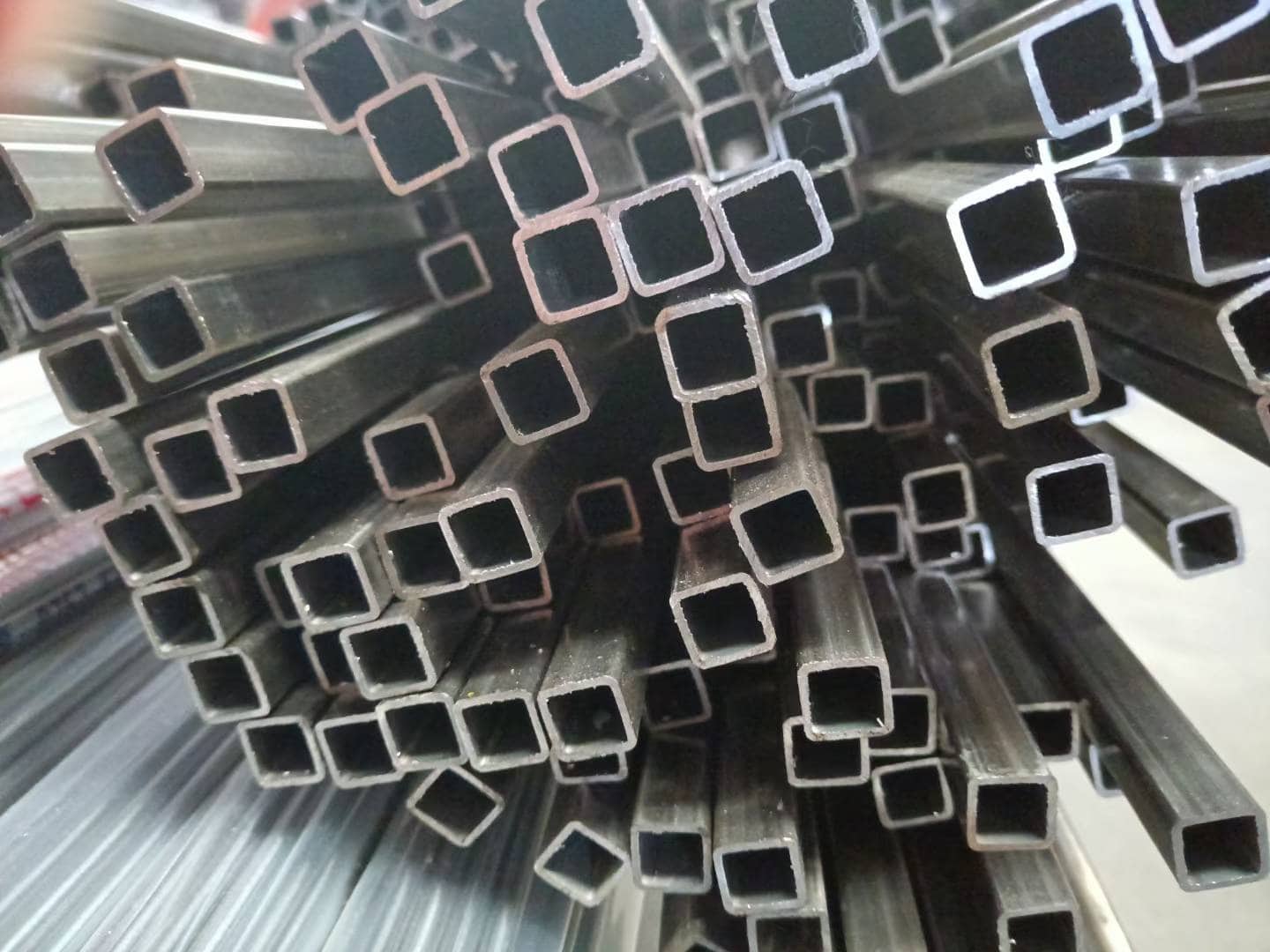
- Square Tubing: Symmetrical sections from 3 × 3 mm to 406.4 × 406.4 mm (16 × 16 in.) with controlled corner radii.
- Rectangular Tubing: Structural profiles with specified outside dimensions across flats and uniform wall thicknesses.
- Special Profiles: Custom architectural shapes including oval, flat-oval (elliptical), D-shaped, and handrail sections.
Applications include architectural balustrades, curtain walls, structural trusses, retail fixtures, and vehicle exhaust lines.
2. Summary of Changes: ASTM A554-26 vs. ASTM A554-21
ASTM A554-26 (approved April 1, 2026) incorporates fourteen technical updates over A554-21. The table below highlights key revisions impacting procurement.
| Revision Item | Clause / Table | Summary of Change in ASTM A554-26 | Engineering & Procurement Impact |
|---|---|---|---|
| Scope Expansion | Sections 1.1 & 1.2 | Added martensitic alloys, annealed, and cold-worked states. | Expands scope for structural components. |
| Chemistry Harmonization | Table 1 | Aligned Table 1 chemistry with A240/A240M. | Eliminates chemistry conflicts with raw coil. |
| Cold-Working Terms | Sections 3.2.1 & 3.2.2 | Defined “cold-formed” vs. “cold-reduced”. | Clarifies temper on purchase orders. |
| Large Diameter Note | Tables 2 & 3 Note 4 | Note 4 added: tolerances over 16 in. by agreement. | Formalizes rules for large cylinders. |
| Extended Structural Sizes | Tables 5, 6, & 7 | Added brackets for 8–12 in. and 12–16 in. | Standardizes heavy structural sizes. |
| Heavy Wall Corner Radii | Table 6 | Extended corner radii up to 0.625 in. wall. | Verifies radii for heavy structural sections. |
| Twist Tolerance Table | Table 7 | A554-26 adds twist tolerances for larger sizes in Table 7. | Ensures alignment in long structural spans. |
| Supplemental Testing Lots | Sections S1.2 & S2.2 | Increased test lots: hardness 1/2,500 ft; tensile 1/5,000 ft. | Optimizes mill testing efficiency. |
3. Delivery Conditions and Inside Diameter (ID) Bead Control
Section 7 defines mechanical delivery conditions and internal weld seam options based on subsequent fabrication requirements.
| Condition / Option | Clause | Code | Process Characteristics |
|---|---|---|---|
| As-Welded | Clause 7.1.1 | As-welded | Supplied directly off the mill without heat treatment; standard for general architectural framing. |
| Welded & Annealed | Clause 7.1.2 | Annealed | Solution annealed to maximize ductility and corrosion resistance for bending and flaring. |
| Cold-Reduced | Clause 7.1.3 | Cold-reduced | Round tubes only; cold-drawn to achieve tighter OD/ID tolerances and higher tensile temper. |
| Bead Not Removed | Clause 7.2.1 | Bead intact | Internal weld flash remains as-welded; standard for decorative handrails and structural trim. |
| Bead Controlled | Clause 7.2.2 | Bead controlled | Weld flash rolled to max 0.005 in. (0.13 mm) or 15% of wall thickness (whichever is greater). |
| Bead Removed | Clause 7.2.3 | Bead removed | Internal flash planished flush with wall; required for internal sleeves or telescoping assemblies. |
Clause 7.3 specifies that square and rectangular tubing is supplied cold-worked unless ordered annealed.
4. Steel Grades and Chemical Composition Limits
Table 1 standardizes austenitic, duplex, ferritic, and martensitic steels. Analysis follows ASTM A751. The table below summarizes representative grades.
| Alloy | UNS | C (%) max | Mn (%) max | P (%) max | S (%) max | Si (%) max | Cr (%) | Ni (%) | Mo (%) | Other Elements (%) |
|---|---|---|---|---|---|---|---|---|---|---|
| 304 | S30400 | 0.08 | 2.00 | 0.045 | 0.030 | 0.75 | 18.0–20.0 | 8.0–11.0 | — | — |
| 304L | S30403 | 0.030 | 2.00 | 0.045 | 0.030 | 0.75 | 18.0–20.0 | 8.0–12.0 | — | — |
| 316 | S31600 | 0.08 | 2.00 | 0.045 | 0.030 | 0.75 | 16.0–18.0 | 10.0–14.0 | 2.00–3.00 | — |
| 316L | S31603 | 0.030 | 2.00 | 0.045 | 0.030 | 0.75 | 16.0–18.0 | 10.0–14.0 | 2.00–3.00 | — |
| 430 | S43000 | 0.12 | 1.00 | 0.040 | 0.030 | 1.00 | 16.0–18.0 | 0.75 | — | — |
| 2205 | S32205 | 0.030 | 2.00 | 0.030 | 0.020 | 1.00 | 22.0–23.0 | 4.5–6.5 | 3.0–3.5 | N: 0.14–0.20 |
Summary based on ASTM A554-26 Table 1; refer to the purchased standard for the full text.
5. Dimensional Tolerances: Round Mechanical Tubing
Round tubing dimensional tolerances are governed by Table 2 for standard conditions (bead intact or bead controlled) and Table 3 for tubing with bead removed. Footnote A specifies that wall thickness tolerance is ±10% of specified wall thickness across all size brackets.
Table 2: Diameter, Wall, and Ovality Tolerances (All Conditions Except Tubing with Bead Removed)
| OD Size, in. (mm) | Wall Thickness (in.) | Wall Thickness (mm) | OD Tolerance (± in.) | OD Tolerance (± mm) | Wall Thickness Tolerance |
|---|---|---|---|---|---|
| Under 1/2 (12.7) | 0.020 to 0.049 | 0.51 to 1.24 | 0.004 | 0.10 | ±10% of specified wall thickness |
| 1/2 to 1 (12.7 to 25.4) | 0.020 to 0.065 | 0.51 to 1.65 | 0.005 | 0.13 | |
| Over 0.065 to 0.134 | Over 1.65 to 3.40 | 0.010 | 0.25 | ||
| Over 1 to 1 1/2 (25.4 to 38.1), incl | 0.025 to 0.065 | 0.64 to 1.65 | 0.008 | 0.20 | |
| Over 0.065 to 0.134 | Over 1.65 to 3.40 | 0.010 | 0.25 | ||
| Over 1 1/2 to 2 (38.1 to 50.8), incl | 0.025 to 0.049 | 0.64 to 1.24 | 0.010 | 0.25 | |
| Over 0.049 to 0.083 | Over 1.24 to 2.11 | 0.011 | 0.28 | ||
| Over 0.083 to 0.149 | Over 2.11 to 3.78 | 0.012 | 0.30 | ||
| Over 2 to 2 1/2 (50.8 to 63.5), incl | 0.032 to 0.065 | 0.81 to 1.65 | 0.012 | 0.30 | |
| Over 0.065 to 0.109 | Over 1.65 to 2.77 | 0.013 | 0.33 | ||
| Over 0.109 to 0.165 | Over 2.77 to 4.19 | 0.014 | 0.36 | ||
| Over 2 1/2 to 3 1/2 (63.5 to 88.9), incl | 0.032 to 0.165 | 0.81 to 4.19 | 0.014 | 0.36 | |
| Over 0.165 | Over 4.19 | 0.020 | 0.51 | ||
| Over 3 1/2 to 5 (88.9 to 127.0), incl | 0.035 to 0.165 | 0.89 to 4.19 | 0.020 | 0.51 | |
| Over 0.165 | Over 4.19 | 0.025 | 0.64 | ||
| Over 5 to 7 1/2 (127.0 to 190.5), incl | 0.049 to 0.250 | 1.24 to 6.35 | 0.025 | 0.64 | |
| Over 0.250 | Over 6.35 | 0.030 | 0.76 | ||
| Over 7 1/2 to 16 (190.5 to 406.4), incl | All | All | 0.00125 in./in. of circumference | 0.00125 mm/mm of circumference |
Table 3: Diameter, Wall, and Ovality Tolerances for Tubing with Bead Removed
When tubing is ordered with the inside bead removed (Clause 7.2.3), Table 3 governs tolerances across both outer and inner diameters:
| OD Size, in. (mm) | OD Tolerance (± in.) | OD Tolerance (± mm) | ID Tolerance (± in.) | ID Tolerance (± mm) | Wall Thickness Tolerance |
|---|---|---|---|---|---|
| Up to 3/32 (2.4), excl | 0.001 | 0.03 | 0.001 | 0.03 | ±10% of specified wall thickness |
| 3/32 to 3/16 (2.4 to 4.8), excl | 0.0015 | 0.038 | 0.0015 | 0.038 | |
| 3/16 to 1/2 (4.8 to 12.7), excl | 0.003 | 0.08 | 0.005 | 0.13 | |
| 1/2 to 1 (12.7 to 25.4), excl | 0.004 | 0.10 | 0.006 | 0.15 | |
| 1 to 1 1/2 (25.4 to 38.1), excl | 0.005 | 0.13 | 0.007 | 0.18 | |
| 1 1/2 to 2 (38.1 to 50.8), excl | 0.006 | 0.15 | 0.008 | 0.20 | |
| 2 to 2 1/2 (50.8 to 63.5), excl | 0.007 | 0.18 | 0.010 | 0.25 | |
| 2 1/2 to 3 1/2 (63.5 to 88.9), excl | 0.010 | 0.25 | 0.014 | 0.36 | |
| 3 1/2 to 5 (88.9 to 127.0), incl | 0.015 | 0.38 | 0.020 | 0.51 | |
| Over 5 to 16 (127.0 to 406.4), incl | 0.00125 in./in. of circumference | 0.00125 mm/mm of circumference | 0.0013 in./in. of circumference | 0.0013 mm/mm of circumference |
Standard Notes on Ovality, Dimensioning, and Large Sizes
Tables 2 and 3 include critical governing notes for round mechanical tubing:
- Note 1 (Ovality Exemption): Ovality is the difference between maximum and minimum outside diameters measured at any one cross section. There is no additional tolerance for ovality on tubes having a specified wall thickness of more than 3% of the outside diameter.
- Note 2 (Thin-Wall Ovality ≤ 5 in.): For sizes up to and including 5 in. (127.0 mm) outside diameter with wall thickness ≤ 3% of OD, an ovality tolerance of twice the tabular outside diameter tolerance spread is applied one-half plus and one-half minus. The average of the maximum and minimum OD readings must fall within the tabular OD tolerances.
- Note 3 (Thin-Wall Ovality 5 to 16 in.): For sizes over 5 in. (127.0 mm) to and including 16 in. (406.4 mm) outside diameter with wall thickness ≤ 3% of OD, ovality shall not exceed 1.5% of the specified outside diameter.
- Note 4 (Tolerances Over 16 in.): For sizes over 16 in. (406 mm), the purchaser shall consult the tube manufacturer regarding tolerances.
- Table 3 Note 3 (Dimensioning Rule): Tubing with bead removed may be specified to only two of the three following dimensions: outside diameter, inside diameter, or wall thickness.
6. Dimensional Tolerances: Square and Rectangular Tubing
Square and rectangular profiles conform to Table 5 (flats), Table 6 (corner radii), and Table 7 (twist).
| Largest Specified Dimension Across Flats | Wall Thickness | Outside Tolerance Across Flats (±) | Wall Thickness Tolerance |
|---|---|---|---|
| To 1 1/4 in. (31.8 mm), incl | All walls | 0.015 in. (0.38 mm) | ±10% of nominal wall thickness |
| Over 1 1/4 to 2 1/2 in. (31.8 to 63.5 mm), incl | All walls | 0.020 in. (0.51 mm) | |
| Over 2 1/2 to 5 1/2 in. (63.5 to 139.7 mm), incl | All walls | 0.030 in. (0.76 mm) | |
| Over 5 1/2 to 8 in. (139.7 to 203.2 mm), incl | All walls | 0.060 in. (1.52 mm) | |
| Over 8 to 12 in. (203.2 to 304.8 mm), incl | All walls | 0.080 in. (2.03 mm) | |
| Over 12 to 16 in. (304.8 to 406.4 mm), incl | All walls | 0.125 in. (3.18 mm) |
Effective Corner Radius (ECR) Formula and Limits
Figure 1 defines the corner radius as Effective Corner Radius (ECR):
ECR = (Profile Width − Width of Flat) / 2
Table 6 specifies maximum corner radii based on wall thickness:
| Specified Wall Thickness, in. (mm) | Maximum Corner Radii (ECR), in. (mm) |
|---|---|
| 0.020 to 0.049 in. (0.51 to 1.24 mm), incl | 3/32 in. (2.4 mm) |
| Over 0.049 to 0.065 in. (1.24 to 1.65 mm), incl | 1/8 in. (3.2 mm) |
| Over 0.065 to 0.095 in. (1.65 to 2.42 mm), incl | 3/16 in. (4.8 mm) |
| Over 0.095 to 0.134 in. (2.42 to 3.40 mm), incl | 17/64 in. (6.8 mm) |
| Over 0.134 to 0.250 in. (3.40 to 6.35 mm), incl | 9/16 in. (14.3 mm) |
| Over 0.250 to 0.625 in. (6.35 to 15.88 mm), incl | 1 7/8 in. (47.6 mm) |
Squareness, Straightness, and Twist Controls (Table 7)
ASTM A554 governs structural profile geometry through three specific tolerances:
- Squareness of Sides: Out-of-square tolerance is calculated as ±B = C × 0.006, where B is the tolerance for out-of-square and C is the length of the longest side.
- Straightness: Maximum camber is 0.075 in. in 3 ft (2.1 mm in 1 m) measured using a 3-ft (1-m) straightedge and feeler gauge.
- Twist Limits: Permissible twist is measured by holding one end flat on a surface plate and measuring elevation at the opposite corners per Table 7:
| Largest Size, in. (mm) | Twist in 3 ft (1 m) max, in. (mm) | Twist in 20 ft (6 m) max, in. (mm) |
|---|---|---|
| Under 1 1/2 (38.1), incl | 0.050 (1.27) | 0.333 (8.45) |
| Over 1 1/2 to 2 1/2 (38.1 to 63.5), incl | 0.062 (1.57) | 0.413 (10.5) |
| Over 2 1/2 to 4 (63.5 to 101.6), incl | 0.075 (1.90) | 0.500 (12.7) |
| Over 4 to 6 (101.6 to 152.4), incl | 0.087 (2.21) | 0.580 (14.7) |
| Over 6 to 8 (152.4 to 203.2), incl | 0.100 (2.54) | 0.667 (16.9) |
| Over 8 (203.2) | 0.112 (2.84) | 0.747 (19.0) |
7. Cut Lengths, Straightness, and Workmanship
Tubing is standardly shipped in mill lengths of 5 ft (1.5 m) and over. Cut lengths conform to Table 4:
| Specified Cut Length | Outside Diameter Size | Over Length Tolerance | Under Length Tolerance |
|---|---|---|---|
| 4 ft (1.2 m) and under | Up to 2 in. (50.8 mm), incl | 1/16 in. (1.6 mm) | 0 mm |
| Over 2 in. (50.8 mm) | 3/32 in. (2.4 mm) | 0 mm | |
| Over 4 to 10 ft (1.2 to 3.0 m), incl | All sizes | 1/8 in. (3.2 mm) | 0 mm |
| Over 10 to 24 ft (3.0 to 7.3 m), incl | All sizes | 3/16 in. (4.8 mm) | 0 mm |
Round straightness is limited to 0.030 in. (0.76 mm) in 3 ft (Section 9.4). Under Section 11, tube ends must be deburred. Surface imperfections are blendable within 10% of wall thickness or 0.002 in. (0.05 mm).
8. Supplementary Requirements: Hardness, Tension, and NDT
Supplementary Requirements S1 through S7 apply only when specified in the order:
| Requirement | Clause | Test Parameters & Acceptance Limits | Application Focus |
|---|---|---|---|
| Hardness Test | S1 & Table S1.1 | 1 test / 2,500 ft (760 m). Max 192 HB / 90 HRB (austenitic); max 190 HB (ferritic); 290–310 HB (duplex). | Verifies formability prior to secondary bending or roll forming. |
| Tension Test | S2 & Table S2.1 | 1 test / 5,000 ft (1,520 m). 304: tensile ≥ 75 ksi (517 MPa), yield ≥ 30 ksi (207 MPa). 304L/316L: tensile ≥ 70 ksi (483 MPa). | Confirms load-bearing strength for architectural trusses and frames. |
| Nondestructive Test | S3 | Various nondestructive tests are available; the test method and inspection limits must be specified in the order. | Seam flaw detection for critical structural or exhaust tubes. |
| Mill Test Reports | S4 | Mill test certificate detailing heat analysis and test data. | Required for quality audits and project material traceability. |
| Annealed Welds | S7 | Post-weld heat treatment for duplex tubing per ASTM A790/A790M. | Restores phase balance and corrosion resistance across welded seams. |
9. Technical Comparison: ASTM A554 vs. ASTM A312
Selecting between ASTM A554 and ASTM A312 is a key engineering decision.
| Feature | ASTM A554-26 | ASTM A312 / A312M |
|---|---|---|
| Primary Scope | Mechanical, ornamental, structural, and exhaust tubing. | Pressure piping for high-temperature and general corrosive service. |
| Profiles Covered | Round, square, rectangular, and special custom shapes (oval, D-shaped). | Round pipes only (standard nominal pipe sizes / schedules). |
| Pressure Testing | None mandatory (supplementary NDT optional under S3). | Each pipe: hydrostatic or nondestructive electric test. |
| Dimensional Focus | Outside dimensions across flats, corner radii (ECR), squareness, and twist. | Nominal Pipe Size (NPS) and Schedule wall thickness per ASME B36.19M. |
| Surface Finish Focus | Cosmetic finishes: satin, brushed, hairline, or No. 8 mirror polishing. | Industrial mill finish (pickled and passivated). |
Design Rule: Never substitute ASTM A554 for pressurized fluid containment; use ASTM A312. For architectural handrails, balustrades, and structural frames, ASTM A554 delivers optimal surface quality and tighter cross-sectional tolerances.
10. Purchase Order Specification Checklist
Include these eight technical parameters on purchase orders:
- Specification: State
ASTM A554-26. - Form & Quantity: Meters, feet, or pieces; shape (Round, Square, Rectangular, or Special).
- Dimensions: Outside dimensions across flats or outer diameter, and specified nominal wall thickness.
- Alloy Grade: State AISI or UNS designation (e.g.,
304 / S30400or316L / S31603). - Delivery Condition: As-welded or welded and annealed (Clause 7.1).
- ID Bead Control: Bead intact, bead controlled (Clause 7.2.2), or bead removed (Clause 7.2.3).
- Surface Finish: Specify mill finish, 180–400 grit satin, hairline, or No. 8 mirror polish with protective PE film.
- Supplementary Options: Required options such as
S1(hardness),S2(tensile), orS4(3.1 MTC).
11. TeCarve Foshan Plant Supply Capabilities: Decorative, Square, Rectangular & Special Profiles
TeCarve is a specialized Chinese stainless steel piping solutions provider and the exclusive factory-direct export channel for two dedicated manufacturing plants in Foshan (welded & decorative tubing) and Wenzhou (seamless & precision tubing). The Foshan Plant specializes in welded mechanical, structural, and ornamental tubing conforming to ASTM A554, EN 10296-2, JIS G3446, and GB/T 18705.
Architectural Decorative & Handrail Tubing
The Foshan Plant supplies ornamental tubing in 304, 304L, 316, and 316L with controlled surface consistency: hairline, 180–400 grit satin, and No. 8 mirror (≥ 8K) with PE film. Review the decorative stainless steel pipe and tubing specifications.
Square Stainless Steel Tubing
The Foshan Plant produces square profiles from 3 × 3 mm to 300 × 300 mm in 304, 316L, and EN 1.4062 duplex (wall 1.5–8.0 mm) with controlled corner radii per Table 6. Explore the stainless steel square pipe and tube product ranges.
Rectangular Stainless Steel Tubing
The Foshan Plant supplies rectangular tubing up to 16 in. envelopes with uniform flats, tight twist tolerances, and EN 10204 3.1 MTCs. Learn more about the stainless steel rectangular pipe and tube solutions.
Oval & Flat-Oval (Elliptical) Tubing
The Foshan Plant maintains 95 existing die sets for oval and flat-oval tubes, enabling custom profiles without tooling charges. Check the custom oval stainless steel tubing profiles.
Custom Special-Shaped Profiles
The Foshan Plant tooling catalogue covers 340+ tooling sizes across 31 profile families (D-shaped, triangle, handrails). Browse the special-shaped stainless steel tube die catalogue.
Pre-Shipment Quality Audits & Plant Verification
All shipments undergo pre-shipment inspection by TeCarve QC inspectors for dimensions, corner radii, and PMI. Plant certificates (including ISO 9001, ISO 14001, ISO 45001 and PED / AD 2000-W0) can be reviewed on https://tecarvepipes.com/verify-our-factories/.
A: No. ASTM A554 is a mechanical and structural tubing specification without mandatory hydrostatic testing. For pressure containment or leak-tight piping, engineers must specify ASTM A312 (process piping) or ASTM A269 (tubing).
A: In ASTM A554 Figure 1, corner radius is defined as Effective Corner Radius: ECR = (Profile Width – Width of Flat) / 2. Table 6 specifies maximum ECR values based on wall thickness to guarantee consistent profile geometry.
A: Key updates include adding martensitic grades and cold-worked definitions, harmonizing Table 1 with ASTM A240/A240M, expanding square/rectangular tables up to 16 in. (406.4 mm), adding twist limits over 8 in., adopting ASTM A700, and increasing test lot sizes.
A: Clause 7.2 provides three options: (1) Bead not removed (as-welded flash); (2) Bead controlled to max 0.005 in. (0.13 mm) or 15% of wall; (3) Bead removed (planished flush for telescoping assemblies).
A: Yes. TeCarve’s Foshan Plant maintains 95 oval/flat-oval dies and over 340 tooling sizes across 31 profile families. When matching an existing die size, tubing is produced without tooling charges.
A: Table 2 applies to round mechanical tubing in all delivery conditions except bead removed, specifying outside diameter tolerances based on diameter and wall thickness brackets. Table 3 applies specifically to round tubing with the inside weld bead removed, providing both outside diameter and inside diameter tolerances for telescoping or sleeve assemblies.