

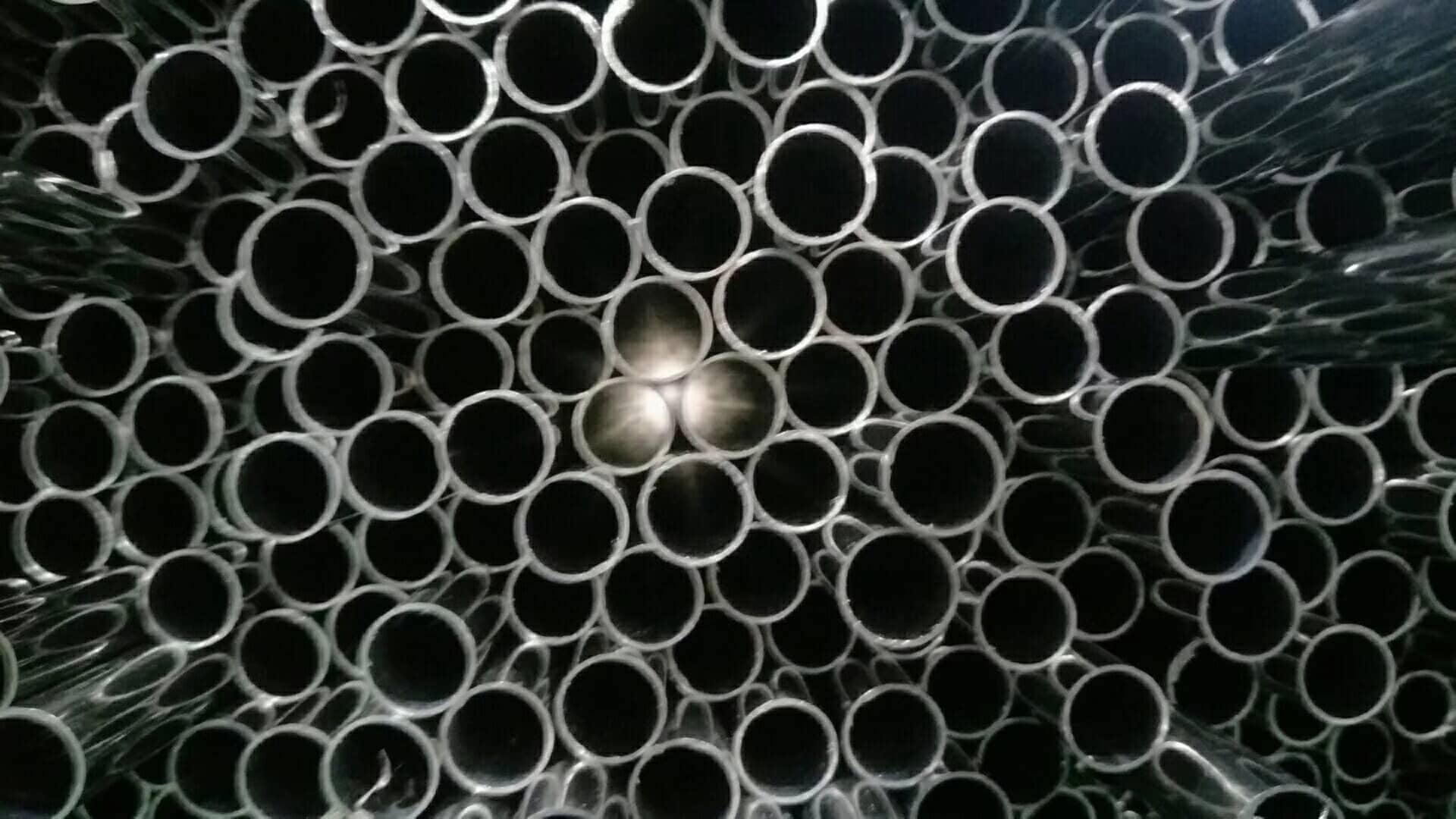

EN 10296-2:2005 specifies technical delivery conditions for welded circular stainless steel tubes used in mechanical and general engineering. Covering austenitic, duplex, and ferritic grades, it standardizes dimensions, weld bead executions, process routes, and verification testing for non-pressure applications.
1. Standard Scope, Applications, and Structural Engineering Context
Prepared by ECISS/TC 29 and adopted across CEN member states by June 2006, EN 10296-2 covers welded circular stainless steel tubes for mechanical and general engineering purposes. Seamless engineering tubes are governed under EN 10297. For pressure vessels, tubes must be ordered to EN 10217-7 welded stainless steel tubes for pressure purposes. For American architectural applications, cross-reference the ASTM A554 mechanical tubing guide.
2. Manufacturing Process, Delivery Conditions, and Weld Bead Finishes
Per Clause 7.2.1, tubes are continuously automatically welded from hot- or cold-rolled strip, sheet, or plate, with or without filler metal. Strip-joining welds are prohibited (jointers permitted only by agreement).
Delivery Conditions (Clause 7.2.2)
- Ferritic Grades: As-welded (+AR) or annealed (+A) at manufacturer’s choice.
- Austenitic & Duplex: As-welded (+AR) or solution annealed (+AT) as specified in the purchase order. Option 3 specifies pickling.
Weld Bead Finishes (Clause 7.2.1)
Selected by the manufacturer unless Option 2 is specified:
- Finish A: Internal and external beads unworked (prohibited for HF welded tube).
- Finish B: External bead removed flush; internal bead unworked.
- Finish C: Internal and external beads rolled or removed flush.
3. Process Routes and Surface Conditions (Table A.1)
Annex A specifies process routes defining starting strip, heat treatment, descaling, and finishing. Selected by manufacturer unless Option 1 is ordered:
| Symbol | Starting Material & Manufacturing Route | Surface Finish & Technical Characteristics |
|---|---|---|
| W0 | Welded from 1D, 2D, 2E, or 2B strip; no heat treatment | As welded; weld discolouration not removed (not for ferritic) |
| W1 | Welded from hot-rolled 1D strip; descaled | Metallically clean; hot-rolled rough texture (not for ferritic) |
| W1A | Welded from hot-rolled 1D strip; heat treated and descaled | Metallically clean; uniform metallurgical structure |
| W1R | Welded from 1D strip; bright heat treated | Smooth, bright reflective surface; protective atmosphere |
| W2 | Welded from cold-rolled 2D, 2E, or 2B strip; descaled | Metallically clean; cold-rolled smooth surface (not for ferritic) |
| W2A | Welded from cold-rolled strip; heat treated and descaled | Metallically clean; uniform corrosion resistance and ductility |
| W2R | Welded from cold-rolled strip; bright heat treated | Smooth, bright reflective surface; protective atmosphere |
| WCA | ≥20% cold reduced before heat treatment; descaled | Recrystallized weld seam; weld scarcely recognizable |
| WCR | ≥20% cold reduced before bright heat treatment | Recrystallized weld seam; bright reflective finish |
| WG | Ground surface (starting from W2, W2A, W2R, WCA, or WCR) | Uniform ground appearance; grit or roughness as agreed |
| WP | Polished surface (starting from W2, W2A, W2R, WCA, or WCR) | Smooth polished surface; roughness Ra value as agreed |
Note: Suffix “b” designates bead-worked tubes (e.g., W2Ab). Routes W0, W1, and W2 are not permitted for ferritic grades.
4. Chemical Composition (Table 1 Selected Grades)
Cast analysis is performed per heat. Table 1 defines chemical limits for standard engineering grades (% max unless range):
| Steel Designation | Steel Number | C (%) | Si (%) | Mn (%) | P (%) | S (%) | Cr (%) | Mo (%) | Ni (%) | Other (%) |
|---|---|---|---|---|---|---|---|---|---|---|
| X5CrNi18-10 | 1.4301 | 0.07 | 1.00 | 2.00 | 0.045 | 0.015 | 17.0–19.5 | — | 8.0–10.5 | N: 0.11 |
| X2CrNi18-9 | 1.4307 | 0.030 | 1.00 | 2.00 | 0.045 | 0.015 | 17.5–19.5 | — | 8.0–10.5 | N: 0.11 |
| X2CrNiMo17-12-2 | 1.4404 | 0.030 | 1.00 | 2.00 | 0.045 | 0.015 | 16.5–18.5 | 2.00–2.50 | 10.0–13.0 | N: 0.11 |
| X5CrNiMo17-12-2 | 1.4401 | 0.07 | 1.00 | 2.00 | 0.045 | 0.015 | 16.5–18.5 | 2.00–2.50 | 10.0–13.0 | N: 0.11 |
| X6CrNiTi18-10 | 1.4541 | 0.08 | 1.00 | 2.00 | 0.045 | 0.015 | 17.0–19.0 | — | 9.0–12.0 | Ti: 5×C to 0.70 |
| X6CrNiMoTi17-12-2 | 1.4571 | 0.08 | 1.00 | 2.00 | 0.045 | 0.015 | 16.5–18.5 | 2.00–2.50 | 10.5–13.5 | Ti: 5×C to 0.70 |
| X6Cr17 (Ferritic) | 1.4016 | 0.08 | 1.00 | 1.00 | 0.040 | 0.015 | 16.0–18.0 | — | — | — |
| X2CrNiN23-4 (Duplex) | 1.4362 | 0.030 | 1.00 | 2.00 | 0.035 | 0.015 | 22.0–24.0 | 0.10–0.60 | 3.5–5.5 | Cu: 0.10–0.60; N: 0.05–0.20 |
| X2CrNiMoN22-5-3 (Duplex) | 1.4462 | 0.030 | 1.00 | 2.00 | 0.035 | 0.015 | 21.0–23.0 | 2.50–3.50 | 4.5–6.5 | N: 0.10–0.22 |
Controlled Sulphur (Option 4): A sulphur content of 0.015% to 0.030% may be specified for improved machinability.
5. Mechanical Properties at Room Temperature (Table 4 Selected Grades)
Mechanical properties apply to wall thicknesses T ≤ 30 mm in the delivered condition:
| Steel Grade | Number | Rp0.2 min (MPa) | Rp1.0 min (MPa) | Rm (MPa) | A (%) Long. | A (%) Trans. | IGC Resistance |
|---|---|---|---|---|---|---|---|
| X6Cr17 | 1.4016 | 240 | 250 | 430 | 20 | 18 | Yes (sensitized note) |
| X2CrTiNb18 | 1.4509 | 230 | 240 | 430 | 18 | 16 | Yes |
| X2CrNi18-9 | 1.4307 | 180 | 215 | 470 | 40 | 35 | Yes |
| X5CrNi18-10 | 1.4301 | 195 | 230 | 500 | 40 | 35 | Yes (sensitized note) |
| X6CrNiTi18-10 | 1.4541 | 200 | 235 | 500 | 35 | 30 | Yes |
| X2CrNiMo17-12-2 | 1.4404 | 190 | 225 | 490 | 40 | 30 | Yes |
| X5CrNiMo17-12-2 | 1.4401 | 205 | 240 | 510 | 40 | 30 | Yes (sensitized note) |
| X6CrNiMoTi17-12-2 | 1.4571 | 210 | 245 | 510 | 35 | 30 | Yes |
| X2CrNiN23-4 (Duplex) | 1.4362 | 400 | — | 600 | 20 | — | Yes |
| X2CrNiMoN22-5-3 (Duplex) | 1.4462 | 450 | — | 700 | 22 | — | Yes |
Notes: IGC tested per EN ISO 3651-2. Footnote (c): IGC resistance is not fulfilled in sensitized or as-welded condition for non-stabilized grades.
6. Dimensions, Tolerances, and Geometric Limits
Nominal outside diameter D and wall thickness T are selected from EN ISO 1127 stainless steel tube dimensions and tolerances. Reference standard dimensions and weights on the pipe sizes and schedule weight chart.
Outside Diameter and Ovality Tolerances (Clause 8.7.3.1)
- D ≤ 168.3 mm: ±0.75% or ±0.3 mm, whichever is greater (includes ovality).
- D > 168.3 mm: ±1.0% (includes ovality).
- Option 10 (Restricted OD): For D ≤ 114.3 mm, ±0.5% or ±0.15 mm, whichever is greater.
Wall Thickness Tolerances (Clause 8.7.3.2)
Excluding the weld seam, wall thickness tolerance is ±10% or ±0.2 mm, whichever is greater. Measured within 100 mm of tube ends (Clause 11.8).
Maximum Weld Seam Height (Table 6)
External weld beads on HF welded tube are removed flush. Table 6 limits internal and external weld seam height:
| Weld Bead Finish | Diameter Range (D) | Max Seam Height for T ≤ 8 mm | Max Seam Height for T > 8 mm |
|---|---|---|---|
| Finish A (Unworked) | All diameters | 0.20T + 0.5 mm | T / 3 |
| Finish B (Ext. flush, Int. unworked) | D ≤ 114.3 mm | 0.06T + 0.3 mm | — |
| Finish B (Ext. flush, Int. unworked) | D > 114.3 mm | 0.05T + 0.5 mm | T / 6 |
| Finish C (Int. and Ext. worked) | All diameters | 0.15 mm | — |
Length Tolerances and Straightness (Clauses 8.5 & 8.7.2, Table 7)
| Length Category | Length Range | Tolerance |
|---|---|---|
| Standard Length | 6000 mm | +100 mm / −0 |
| Random Length (Option 8) | Agreed length range | Per agreement |
| Exact Length (Option 9) | L ≤ 6000 mm | +5 mm / −0 |
| Exact Length (Option 9) | 6000 mm < L ≤ 12000 mm | +10 mm / −0 |
| Exact Length (Option 9) | L > 12000 mm | Per agreement |
Straightness (Clause 8.5): For D ≥ 33.7 mm, deviation from a straight line shall not exceed 0.0020 L (2 mm/m). Under Option 7, enhanced straightness of ≤ 0.0015 L applies. For D < 33.7 mm, straightness is agreed. Ends are square cut and free from excessive burrs (Clause 8.6).
7. Inspection, Verification Testing, and Quality Control
Unless Option 11 (Specific Inspection) is specified, tubes undergo non-specific inspection per EN 10021.
Inspection and Testing Matrix (Table 8)
For specific inspection, tests are conducted per test unit (Table 9):
- Cast Analysis: 1 test per cast.
- Tensile Test: 1 test per test unit.
- Forming Test (D ≤ 150 mm): 1 test per test unit (flattening per EN ISO 8492 to 67% OD, drift expanding per EN ISO 8493, or full-section bend 180° for D ≤ 65 mm).
- Ring Tensile or Weld Bend (D > 150 mm): 1 test per test unit (weld bend per EN 910 with 6T mandrel).
- Material Identification: Tested on each tube to verify grade conformity.
- Leak Tightness (Option 6) & Weld NDT (Option 5): Individual testing on each tube.
Test Unit Sizes (Table 9)
For max tube length 20 m: D ≤ 114.3 mm (400 tubes); 114.3 mm < D ≤ 323.9 mm (200 tubes); D > 323.9 mm (100 tubes).
Leak Tightness Testing (Clause 11.7, Option 6)
Electromagnetic (EN 10246-2) or hydrostatic at manufacturer’s choice (unless Option 14); SAW tubes use hydrostatic. Test pressure is calculated by:
P = 20 × S × T / D
where P is bar, D is OD (mm), T is wall (mm), and S is stress (70% of min Rp0.2 in MPa). Pressure is capped at 70 bar, held ≥5 s (D ≤ 457 mm) or ≥10 s (D > 457 mm).
Weld NDT (Clause 11.10, Option 5)
Full-length weld NDT per EN 10246-3 (E3/E3H for wall ≤ 6 mm), EN 10246-7/8/9 (U4), or EN 10246-10 (R2 class). Personnel qualify to EN 10256.
8. Mill Inspection Documents (Clause 9.2)
Documentation conforms to EN 10204:
- Non-Specific: Declaration of compliance 2.1 (test report 2.2 under Option 12).
- Specific (Option 11): Inspection certificate 3.1 (certificate 3.2 under Option 13). Review certification criteria in the EN 10204 3.1 mill test certificate guide.
9. Purchaser Options (Clause 6.2) and Ordering Guide
Clause 6.2 defines fourteen options to specify tube execution and testing rigor:
| Option # | Clause Reference | Option Description & Technical Scope |
|---|---|---|
| Option 1 | Clause 7.2.1 / Table A.1 | Process route and surface condition specified by purchaser |
| Option 2 | Clause 7.2.1 | Weld bead finish specified (Finish A, B, or C) |
| Option 3 | Clause 7.2.2 | Tubes supplied with pickled surface finish |
| Option 4 | Clause 8.2 / Table 1 | Controlled sulphur content (0.015% to 0.030%) for enhanced machinability |
| Option 5 | Clause 8.4.2 / 11.10 | Full-length weld NDT on each tube (specific inspection only) |
| Option 6 | Clause 8.4.2 / 11.7 | Leak tightness testing of each tube (hydrostatic or electromagnetic) |
| Option 7 | Clause 8.5 | Restricted straightness tolerance ≤ 0.0015 L for D ≥ 33.7 mm |
| Option 8 | Clause 8.7.2 / Table 7 | Random lengths ordered to an agreed length range |
| Option 9 | Clause 8.7.2 / Table 7 | Exact lengths ordered to specific cut length tolerances |
| Option 10 | Clause 8.7.3.1 | Restricted OD tolerance ±0.5% or ±0.15 mm for D ≤ 114.3 mm |
| Option 11 | Clause 9.1 | Specific inspection ordered per EN 10021 |
| Option 12 | Clause 9.2.1 | Test report 2.2 supplied for non-specific inspection |
| Option 13 | Clause 9.2.2 | Inspection certificate 3.2 supplied for specific inspection |
| Option 14 | Clause 11.7 | Leak-tightness test method chosen by purchaser |
Example Order Designation (Clause 6.3)
A typical inquiry follows the normative standard format:
15 t – Tube – 60.3 x 3.2 – EN 10296-2 – 1.4301+AT – option 12
This designates 15 tonnes of circular welded tube with outside diameter 60.3 mm and wall thickness 3.2 mm, manufactured to EN 10296-2 in grade 1.4301, solution annealed (+AT), in standard 6000 mm lengths with an EN 10204 test report 2.2.
10. TeCarve Supply Range: Welded Stainless Mechanical Tubing
TeCarve serves as the exclusive factory-direct export channel for two dedicated manufacturing plants in Foshan (welded & decorative tubing) and Wenzhou (seamless & precision tubing).
Foshan Plant: Welded & Architectural Stainless Steel Tubing
The welded product page lists TIG, plasma, laser and ERW welded pipe and tube in grades 201, 202, 304, 304L, 316, 316L, 409, 410, 430 and Duplex (OD 6–4200 mm, wall 0.5–120 mm). Explore the welded stainless steel pipe catalog and architectural tubing on the stainless steel decoration pipe page.
Plant Quality Certifications
Plant certificates (including ISO 9001, ISO 14001, ISO 45001 and PED / AD 2000-Merkblatt W0) are held by the plants — see https://tecarvepipes.com/verify-our-factories/.
A: EN 10296-2 specifies technical delivery conditions for welded circular stainless steel tubes used for mechanical and general engineering purposes.
A: EN 10296-2 governs tubes for mechanical and general engineering with non-specific inspection as standard, whereas EN 10217-7 covers welded stainless tubes for pressure purposes; see our EN 10217-7 guide for its requirements. In EN 10296-2, leak tightness and weld NDT are optional (Options 6 and 5).
A: +AR designates the as-welded condition without heat treatment, while +AT indicates solution annealing for austenitic and duplex grades .
A: Finish A retains internal and external weld beads. Finish B removes the external bead flush while retaining the internal bead. Finish C rolls or removes both internal and external beads flush.
A: Neither test is mandatory under standard non-specific inspection. Full-length weld NDT requires Option 5, and leak tightness testing requires Option 6.
A: Non-specific inspection provides an EN 10204 declaration of compliance 2.1 (or test report 2.2 under Option 12). If specific inspection is ordered via Option 11, an inspection certificate 3.1 (or 3.2 under Option 13) is issued.
Summary based on EN 10296-2:2005; refer to the purchased standard for the full text.