

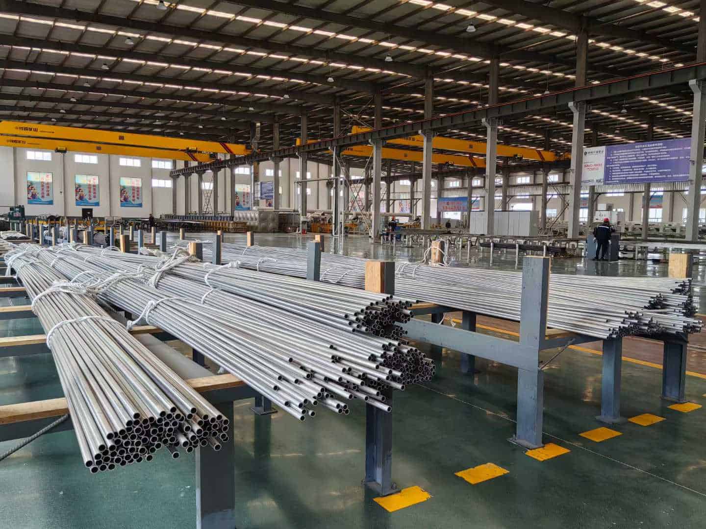

ASTM A999/A999M-23 is the general requirements specification governing alloy and stainless steel pipe under standards such as ASTM A312, ASTM A358, and ASTM A790. It standardizes dimensional tolerances, hydrostatic test pressures, nondestructive examination (NDE), mechanical testing, and certification criteria.
1. Standard Scope, Applicable Product Specifications, and Conflict Rules
ASTM A999/A999M (ASME SA-999) is maintained by ASTM Committee A01 and Subcommittee A01.10. Approved and published in September 2023, ASTM A999/A999M-23 supersedes the 2018 edition.
Per Clause 1.1, ASTM A999 applies to 19 product standards unless modified by the governing specification: ASTM A312, A333, A335, A358, A369, A376, A409, A426, A451, A608, A778, A790, A813, A814, A872, A928, A943, A949, and A954.
Conflict Hierarchy (Clause 1.2): The product specification prevails over ASTM A999. A more stringent requirement in the purchase order prevails over both.
Units (Clause 1.3): Inch-pound units govern unless the “M” designation (ASTM A999M) is specified in the purchase order.
2. Permissible Variations in Wall Thickness (Tables 1 and 2)
Section 9 governs wall thickness tolerances for seamless and welded pipe ordered to nominal or minimum wall.
Nominal Wall Thickness Tolerances (Table 1)
When ordered to nominal wall thickness (Section 9.1), under-tolerance is fixed at −12.5% across all sizes, while over-tolerance varies with nominal pipe size (NPS), manufacturing process, and wall thickness-to-outside diameter ratio (t/D):
| NPS Designator [DN] | t/D Ratio Range | Tolerance Over Nominal (%) | Tolerance Under Nominal (%) |
|---|---|---|---|
| NPS 1/8 to 2-1/2 incl. [DN 6 to 65] | All t/D ratios | +20.0% | −12.5% |
| NPS 3 to 18 incl. [DN 80 to 450] | Up to 5% incl. | +22.5% | −12.5% |
| NPS 3 to 18 incl. [DN 80 to 450] | Over 5% | +15.0% | −12.5% |
| NPS 20 and larger [DN 500+], Welded | All t/D ratios | +17.5% | −12.5% |
| NPS 20 and larger [DN 500+], Seamless | Up to 5% incl. | +22.5% | −12.5% |
| NPS 20 and larger [DN 500+], Seamless | Over 5% | +15.0% | −12.5% |
Minimum Wall Thickness Tolerances (Table 2)
When ordered to minimum wall thickness (Section 9.1.1), zero under-tolerance is permitted (0.0%), with over-tolerances defined in Table 2:
| NPS Designator [DN] | t/D Ratio Range | Tolerance Over Minimum (%) | Tolerance Under Minimum (%) |
|---|---|---|---|
| NPS 1/8 to 2-1/2 incl. [DN 6 to 65] | All t/D ratios | +32.5% | 0.0% |
| NPS 3 to 18 incl. [DN 80 to 450] | Up to 5% incl. | +35.0% | 0.0% |
| NPS 3 to 18 incl. [DN 80 to 450] | Over 5% | +27.5% | 0.0% |
| NPS 20 and larger [DN 500+], Welded | All t/D ratios | +30.0% | 0.0% |
| NPS 20 and larger [DN 500+], Seamless | Up to 5% incl. | +35.0% | 0.0% |
| NPS 20 and larger [DN 500+], Seamless | Over 5% | +27.5% | 0.0% |
Forged/bored pipe (Section 9.2) wall thickness tolerance is +1/8 in [3.2 mm] / −0. Cast pipe (Section 9.3) is +1/16 in [1.6 mm] / −0. Inside diameter (Section 10) for forged/bored and cast pipe is +0 / −1/16 in [1.6 mm].
Inspection Minimum Wall Formula (Appendix X1): Minimum wall thickness on inspection (tm) for nominal wall pipe is:
tm = 0.875 × tn
where tn is nominal wall thickness. Cross-reference dimensions on the pipe sizes and schedule weight chart.
3. Permissible Variations in Outside Diameter and Ovality (Table 3)
Section 11 specifies outside diameter (OD) tolerances across standard sizes. Table 3 governs permissible OD variations, including ovality, except for thin-wall pipe:
| NPS Designator [DN] | Permissible Over Variation (in [mm]) | Permissible Under Variation (in [mm]) |
|---|---|---|
| NPS 1/8 to 1-1/2 incl. [DN 6 to 40] | +1/64 in (0.015 in) [+0.4 mm] | −1/32 in (0.031 in) [−0.8 mm] |
| Over 1-1/2 to 4 incl. [over DN 40 to 100] | +1/32 in (0.031 in) [+0.8 mm] | −1/32 in (0.031 in) [−0.8 mm] |
| Over 4 to 8 incl. [over DN 100 to 200] | +1/16 in (0.062 in) [+1.6 mm] | −1/32 in (0.031 in) [−0.8 mm] |
| Over 8 to 18 incl. [over DN 200 to 450] | +3/32 in (0.093 in) [+2.4 mm] | −1/32 in (0.031 in) [−0.8 mm] |
| Over 18 to 26 incl. [over DN 450 to 650] | +1/8 in (0.125 in) [+3.2 mm] | −1/32 in (0.031 in) [−0.8 mm] |
| Over 26 to 34 incl. [over DN 650 to 850] | +5/32 in (0.156 in) [+4.0 mm] | −1/32 in (0.031 in) [−0.8 mm] |
| Over 34 to 48 incl. [over DN 850 to 1200] | +3/16 in (0.187 in) [+4.8 mm] | −1/32 in (0.031 in) [−0.8 mm] |
Thin-Wall Ovality Rule (Section 11.2): For thin-wall pipe (nominal wall ≤3% of specified OD), Table 3 tolerances apply to the mean of maximum and minimum OD in any cross section. Under Section 11.2.1, ovality (maximum minus minimum OD) shall not exceed 1.5% of specified OD (Note 2 highlights out-of-roundness from final annealing/straightening).
4. Length, End Finish, and Straightness Requirements
Execution requirements are defined across Sections 12 through 15:
- Length (Section 12): Cut lengths ≤24 ft [7.3 m] for seamless and welded pipe (without filler metal) have tolerances of −0 / +1/4 in [6 mm]; >24 ft is by agreement. Forged/bored and cast pipe tolerances are −0 / +1/8 in [3 mm]. Jointers are prohibited unless agreed (12.4).
- Dimensions (Section 13): Conforms to ANSI B36.10 and B36.19; other dimensions are permitted.
- Ends (Section 14): Plain cut with burrs removed, unless beveled or threaded ends are ordered.
- Straightness (Section 15): Metal-arc welded pipe maximum camber is 1/8 in [3.2 mm] per 10 ft [3.0 m] straightedge.
5. Hydrostatic Testing Rules vs. Nondestructive Electric Examination
Section 21 testing applies when invoked by the governing product specification (such as ASTM A312 or ASTM A790) or the purchase order. The manufacturer selects hydrostatic testing (21.2) or nondestructive electric examination (21.3).
Hydrostatic Test Rules (Section 21.2)
Hydrostatic test pressure is calculated by:
P = 2St / D
where P is test pressure (psi [MPa]), S is fiber stress (psi [MPa]), t is specified wall (in [mm]), and D is specified OD (in [mm]). Stress S is ≥60% SMYS for ferritic alloy/stainless, or ≥50% SMYS for austenitic/duplex (Section 21.2.1). Pressures round to the nearest 50 psi [0.5 MPa] below 1000 psi [7 MPa], and nearest 100 psi [1 MPa] at or above. Review pressure ratings on the pipe and tube pressure rating chart. Test pressure cap is 2500 psi [17.0 MPa] for OD ≤3.5 in [88.9 mm], or 2800 psi [19.0 MPa] for OD >3.5 in (Section 21.2.2), held for ≥5 seconds.
Nondestructive Electric Examination (NDE) Options (Section 21.3)
Section 21.3.1 permits ultrasonic (ASTM E213), eddy current (ASTM E426/E309), or flux leakage (ASTM E570) at the manufacturer’s choice. Weld seam UT per ASTM E273 may be added by agreement.
| NDE Method | Standard Reference | Calibration Threshold & Parameters |
|---|---|---|
| Ultrasonic Testing (UT) | ASTM E213 | Longitudinal notches OD/ID; depth ≤12.5% wall or 0.004 in [0.1 mm]; width ≤2× depth; transducer ≥2.0 MHz, size ≤1.5 in [38 mm] |
| Eddy Current Testing (ET) | ASTM E426 / E309 | Max hole dia: NPS 1/2: 0.039 in [1.0 mm]; >1/2–1-1/4: 0.055 [1.4]; >1-1/4–2: 0.071 [1.8]; >2–5: 0.087 [2.2]; >5: 0.106 [2.7] |
| ET Max Frequency | Section 21.3.7.2 | Wall ≤0.050 in [1.3 mm]: 100 kHz; wall ≤0.150 in [3.8 mm]: 50 kHz; wall ≥0.150 in: 10 kHz |
| Flux Leakage (FL) | ASTM E570 | Reference standard per 21.3.8 at the manufacturer’s option |
| Operator Qualification | Sections 21.3.6 / 21.3.9 | Personnel qualified to SNT-TC-1A or equivalent; equipment standardized at intervals ≤4 hours |
6. Mechanical Testing, Chemical Analysis, and Weld Repair Rules
Testing and repair protocols are defined across Sections 6 through 20:
- Chemical Analysis (Section 6): Governed by ASTM A751 per heat. Unspecified elements shall not be added to conform to another grade (6.2.1).
- Mechanical Testing (Sections 7 & 8): Conducted per ASTM A370 (Annex A2) or ASTM A1058 (metric) at room temperature. Yield strength is determined at 0.2% offset or 0.5% extension.
- Flattening Test (Section 20): Applies to seamless ≥2-1/2 in [60 mm] and welded ≥4 in [100 mm] (weld at 90°): H = (1 + e)t / (e + t/D), with e = 0.09 (austenitic/duplex/low-carbon) or 0.08 (ferritic). Cracks at 6 and 12 o’clock are not rejectable when D/t < 10.
- Repair Welding (Section 16): Requires purchaser approval. Procedures and welders qualify to ASME Section IX. Completed repairs require heat treatment, NDT, and marking “WR” (25.4).
- Retests & Retreatment (Sections 17 & 18): Retesting requires double specimens from the same lot. Reheat treatment is limited to twice without purchaser approval.
7. Certification, Inspection, and Product Marking Rules
Quality documentation and product identification follow strict requirements:
- Inspection Access (Section 22): Purchaser inspectors have access to manufacturing facilities during production.
- Mill Certification (Section 24): Test reports record heat analysis, tensile properties, flattening results, hydrostatic test pressures, and NDE methods. EDI test reports carry equal validity. For European documentation, cross-reference the EN 10204 3.1 mill test certificate guide.
- Product Marking (Section 25): Marked starting ~12 in [300 mm] from the end with manufacturer brand, specification designation, and grade. Pipe <NPS 2 or <3 ft [1 m] may be bundle-tagged. Austenitic marking ink must be free of zinc, lead, and copper.
8. Technical Ordering Checklist (Clause 5.1)
Under Section 5.1 of ASTM A999, orders and inquiries should specify:
- Standard & Year: Product specification and edition (e.g., ASTM A312-23 or A790-23).
- Product: Seamless or welded pipe.
- Quantity: Total feet, metres, or number of lengths.
- Manufacturing Method: Seamless, welded (with/without filler metal), or forged and bored.
- Melting Practice: Special melting process if required.
- Grade: Material grade or UNS designation (e.g., TP304L, TP316L, UNS S31803 / S32205).
- Size & Wall Basis: NPS, OD, schedule, and wall basis (nominal wall 9.1, minimum wall 9.1.1, or minimum ID 10.1).
- Length: Specific cut lengths or random lengths.
- End Finish: Plain end or beveled end.
- Testing Options: Hydrostatic test vs. NDE (UT, ET, FL), product analysis, or weld seam UT.
- General Requirements: ASTM A999 or ASME SA-999 with edition year.
- Supplementary Requirements: Purchaser requirements (e.g., Section 27 government procurement).
9. Summary of Key Revisions: ASTM A999/A999M-23 vs. A999/A999M-18
ASTM lists the following changes since A999/A999M-18 (approved Sept. 1, 2023):
| Change listed in A999/A999M-23 Summary of Changes |
|---|
| Revised 5.1.7 (ordering size) to match the new Sections 9 and 10. |
| Deleted former Section 9 and renumbered former Section 10 as Section 9. |
| Revised the new Section 9 to use dimensions in place of mass. |
| Added Table 1 and Table 2 with DN units. |
| Deleted 14.2 and 14.3. |
10. TeCarve Supply Range: Seamless and Welded Stainless Steel Piping
TeCarve serves as the exclusive factory-direct export channel for two dedicated manufacturing plants in Foshan (welded & decorative tubing) and Wenzhou (seamless & precision tubing).
Wenzhou Plant: Seamless Stainless Steel Pipe & Tube
The Wenzhou plant produces cold-drawn and cold-rolled seamless pipes in grades 304, 304L, 316, 316L, and Duplex 2205 (OD 6–1600 mm, wall 0.5–100 mm). The seamless product page lists ASTM A312 and ASTM A999 among its standards. Explore seamless stainless steel pipe specifications.
Foshan Plant: Welded Stainless Steel Pipe & Tube
The Foshan facility manufactures welded pipe via automated TIG, plasma, laser, and ERW welding in grades 201, 202, 304, 304L, 316, 316L, 409, 410, 430, and Duplex 2205 (OD 6–4200 mm, wall 0.5–120 mm). The welded product page lists ASTM A312, ASTM A358 and ASTM A999 among its standards. Explore welded stainless steel pipe specifications.
Plant Certifications
Plant certificates (including ISO 9001, ISO 14001, ISO 45001 and PED / AD 2000-Merkblatt W0, held by the plants) can be reviewed on https://tecarvepipes.com/verify-our-factories/.
A: ASTM A999/A999M establishes general requirements—dimensional tolerances, hydrotest formulas, NDE methods, and mill certification—governing alloy and stainless pipe standards like ASTM A312 and A790.
A: Under Clause 1.2, product specifications prevail over ASTM A999. A more stringent requirement in the purchase order prevails over both.
A: Nominal wall (Table 1) permits −12.5% under-tolerance and +15.0% to +22.5% over-tolerance. Minimum wall (Table 2) permits 0.0% under-tolerance and +27.5% to +35.0% over-tolerance.
A: For thin-wall pipe (wall ≤3% of OD), Table 3 tolerances apply to mean OD. Total ovality (max minus min OD) shall not exceed 1.5% of specified OD.
A: Neither test is mandatory by ASTM A999 alone; testing applies only when invoked by the governing product specification (e.g., A312) or purchase order.
A: Nonmandatory Appendix X1 specifies that minimum inspection wall thickness is calculated by tm = 0.875 × tn, reflecting the −12.5% under-tolerance on nominal wall tn.
Summary based on ASTM A999/A999M-23; refer to the purchased standard for the full text.