

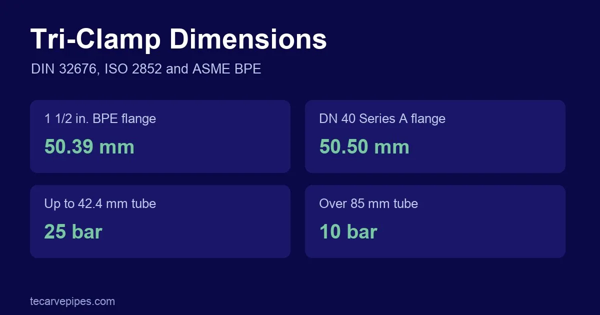

Tri-clamp dimensions are set by the ferrule, not by the tube size alone. A 1 1/2 in. ASME BPE ferrule, a DN 40 Series A ferrule to DIN 32676 and a 38 mm ferrule to ISO 2852 all have a flange of about 50.5 mm, which is the dimension a clamp has to fit. The tube ends and bores still differ, so check the bore and the clamp before you mix standards.
Dimensions are from DIN 32676:2025-09 (Tables 3, 4 and 5), ASME BPE-2026 (Table DT-7.1-1) and ISO 2852:1993 (Tables 1 and 2). All values are in mm unless marked. “Tri-clamp” is the common trade term; the standards call these clamp connections, clamp pipe couplings or hygienic clamp ferrules.
Tri-clamp size chart by flange diameter
This chart groups the three standards by ferrule flange outside diameter, which is the figure a clamp has to fit. It is built from the tables below. BPE flange diameters are inch values and differ slightly from the metric figure, for example 50.39 mm against 50.50 mm.
| Ferrule flange OD, mm (nominal) | ASME BPE size | DIN 32676 Series A | DIN 32676 Series B | DIN 32676 Series C, tube OD mm | ISO 2852 nominal size, mm |
|---|---|---|---|---|---|
| 25 | 1/4 in., 3/8 in., 1/2 in., 3/4 in. | DN 6, DN 8 | DN 6, DN 8, DN 10 | 6.35, 9.53, 12.70, 19.05 | – |
| 34 | 1 in. (Type A) | DN 10, DN 15, DN 20 | – | – | 12 *, 12.7 *, 17.2 *, 21.3 * |
| 50.5 | 1 in. (Type B), 1 1/2 in. | DN 25, DN 32, DN 40 | DN 15, DN 20, DN 25 | 25.40, 38.10 | 25, 33.7, 38 |
| 64 | 2 in. | DN 50 | DN 32, DN 40 | 50.80 | 40, 51 |
| 77.5 | 2 1/2 in. | – | DN 50 | 63.50 | 63.5 |
| 91 | 3 in. | DN 65 | DN 65 | 76.20 | 70, 76.1 |
| 106 | – | DN 80 | DN 80 | – | 88.9 |
| 119 | 4 in. | DN 100 | – | 101.60 | 101.6 |
| 130 | – | – | DN 100 | – | 114.3 |
| 155 | – | DN 125 | DN 125 | – | 139.7 |
| 167 | 6 in. | – | – | 152.40 | – |
| 183 | – | DN 150 | DN 150 | – | 168.3 |
| 233.5 | – | DN 200 | DN 200 | – | 219.1 |
* ISO 2852 Table 1, expanded-type liner. Note that 21.3 mm differs between standards: the flange is 34 mm in ISO 2852 and 50.5 mm in DIN 32676 Series B.
Same flange does not mean a perfect match. The groove and bore can differ between standards. DIN 32676 asks for a transition at the inner surface of ferrule and gasket that is as free of steps as possible, so compare the bore d with the gasket before mixing parts.
DIN 32676 dimensions
DIN 32676 covers clamp connections for butt welding to tube sizes in DIN 11866 and DIN EN 10357. The long version KL is intended for orbital welding. The 2025-09 edition corrected the overall length of the short version in Table 5, so older copies show different figures there.
Series A (DIN 11866, EN 10357) — Table 3
| DN | Tube, mm | Form | Tube OD D | Bore d | Flange OD DF | Groove dN | Flange thickness lF | Length, short KK | Length, long KL |
|---|---|---|---|---|---|---|---|---|---|
| 6 | 8 × 1 | A | 8.00 | 6.00 | 25.00 | 20.20 | 3.60 | 25.4 | 57.2 |
| 8 | 10 × 1 | A | 10.00 | 8.00 | 25.00 | 20.20 | 3.60 | 25.4 | 57.2 |
| 10 | 13 × 1.5 | B | 13.00 | 10.00 | 34.00 | 27.50 | 2.85 | 37.7 | 58.9 |
| 15 | 19 × 1.5 | B | 19.00 | 16.00 | 34.00 | 27.50 | 2.85 | 37.7 | 58.9 |
| 20 | 23 × 1.5 | B | 23.00 | 20.00 | 34.00 | 27.50 | 2.85 | 37.7 | 58.9 |
| 25 | 29 × 1.5 | B | 29.00 | 26.00 | 50.50 | 43.50 | 2.85 | 44.7 | 73.7 |
| 32 | 35 × 1.5 | B | 35.00 | 32.00 | 50.50 | 43.50 | 2.85 | 44.7 | 73.7 |
| 40 | 41 × 1.5 | B | 41.00 | 38.00 | 50.50 | 43.50 | 2.85 | 44.7 | 73.7 |
| 50 | 53 × 1.5 | B | 53.00 | 50.00 | 64.00 | 56.50 | 2.85 | 44.7 | 73.7 |
| 65 | 70 × 2 | B | 70.00 | 66.00 | 91.00 | 83.50 | 2.85 | 57.7 | 97.7 |
| 80 | 85 × 2 | B | 85.00 | 81.00 | 106.00 | 97.00 | 2.85 | 57.7 | 97.7 |
| 100 | 104 × 2 | B | 104.00 | 100.00 | 119.00 | 110.00 | 2.85 | 57.7 | 97.7 |
| 125 | 129 × 2 | B | 129.00 | 125.00 | 155.00 | 146.00 | 5.60 | 57.7 | 133.7 |
| 150 | 154 × 2 | B | 154.00 | 150.00 | 183.00 | 174.00 | 5.60 | 57.7 | 133.7 |
| 200 | 204 × 2 | B | 204.00 | 200.00 | 233.50 | 225.00 | 5.60 | 57.7 | 133.7 |
Series B (DIN 11866) — Table 4
| DN | Tube, mm | Form | Tube OD D | Bore d | Flange OD DF | Groove dN | Flange thickness lF | Length, short KK | Length, long KL |
|---|---|---|---|---|---|---|---|---|---|
| 6 | 10.2 × 1.6 | A | 10.20 | 7.00 | 25.00 | 20.20 | 3.60 | 25.4 | 57.2 |
| 8 | 13.5 × 1.6 | A | 13.50 | 10.30 | 25.00 | 20.20 | 3.60 | 25.4 | 57.2 |
| 10 | 17.2 × 1.6 | A | 17.20 | 14.00 | 25.00 | 20.20 | 3.60 | 25.4 | 57.2 |
| 15 | 21.3 × 1.6 | B | 21.30 | 18.10 | 50.50 | 43.50 | 2.85 | 44.7 | 73.7 |
| 20 | 26.9 × 1.6 | B | 26.90 | 23.70 | 50.50 | 43.50 | 2.85 | 44.7 | 73.7 |
| 25 | 33.7 × 2 | B | 33.70 | 29.70 | 50.50 | 43.50 | 2.85 | 44.7 | 73.7 |
| 32 | 42.4 × 2 | B | 42.40 | 38.40 | 64.00 | 56.50 | 2.85 | 44.7 | 73.7 |
| 40 | 48.3 × 2 | B | 48.30 | 44.30 | 64.00 | 56.50 | 2.85 | 44.7 | 73.7 |
| 50 | 60.3 × 2 | B | 60.30 | 56.30 | 77.50 | 70.50 | 2.85 | 57.7 | 73.7 |
| 65 | 76.1 × 2 | B | 76.10 | 72.10 | 91.00 | 83.50 | 2.85 | 57.7 | 97.7 |
| 80 | 88.9 × 2.3 | B | 88.90 | 84.30 | 106.00 | 97.00 | 2.85 | 57.7 | 97.7 |
| 100 | 114.3 × 2.3 | B | 114.30 | 109.70 | 130.00 | 122.00 | 2.85 | 57.7 | 97.7 |
| 125 | 139.7 × 2.6 | B | 139.70 | 134.50 | 155.00 | 146.00 | 5.60 | 57.7 | 133.7 |
| 150 | 168.3 × 2.6 | B | 168.30 | 163.10 | 183.00 | 174.00 | 5.60 | 57.7 | 133.7 |
| 200 | 219.1 × 2.6 | B | 219.10 | 213.90 | 233.50 | 225.00 | 5.60 | 57.7 | 133.7 |
Series C (DIN 11866, EN 10357) — Table 5
| Tube OD | Tube, mm | Form | Tube OD D | Bore d | Flange OD DF | Groove dN | Flange thickness lF | Length, short KK | Length, long KL |
|---|---|---|---|---|---|---|---|---|---|
| 6.35 | 6.35 × 0.89 | A | 6.35 | 4.57 | 25.00 | 20.20 | 3.60 | 25.4 | 57.2 |
| 9.53 | 9.53 × 0.89 | A | 9.53 | 7.75 | 25.00 | 20.20 | 3.60 | 25.4 | 57.2 |
| 12.70 | 12.7 × 1.65 | A | 12.70 | 9.40 | 25.00 | 20.20 | 3.60 | 25.4 | 57.2 |
| 19.05 | 19.05 × 1.65 | A | 19.05 | 15.75 | 25.00 | 20.20 | 3.60 | 25.4 | 57.2 |
| 25.40 | 25.4 × 1.65 | B | 25.40 | 22.10 | 50.50 | 43.50 | 2.85 | 44.7 | 73.7 |
| 38.10 | 38.1 × 1.65 | B | 38.10 | 34.80 | 50.50 | 43.50 | 2.85 | 44.7 | 73.7 |
| 50.80 | 50.8 × 1.65 | B | 50.80 | 47.50 | 64.00 | 56.50 | 2.85 | 44.7 | 73.7 |
| 63.50 | 63.5 × 1.65 | B | 63.50 | 60.20 | 77.50 | 70.50 | 2.85 | 57.7 | 73.7 |
| 76.20 | 76.2 × 1.65 | B | 76.20 | 72.90 | 91.00 | 83.50 | 2.85 | 57.7 | 97.7 |
| 101.60 | 101.6 × 2.11 | B | 101.60 | 97.38 | 119.00 | 110.00 | 2.85 | 57.7 | 97.7 |
| 152.40 | 152.4 × 2.77 | B | 152.40 | 146.86 | 167.00 | 156.50 | 5.60 | 57.7 | 133.7 |
Selected tolerances: flange thickness is ±0.06 mm for 3.60 and 5.60 mm flanges and ±0.05 mm for 2.85 mm flanges. Flange OD on metallic parts is to h11 and the groove to N11, except on the small Form A flange, which is +0.20/0 mm.
Pressure and temperature
| Tube OD, mm | Permitted pressure |
|---|---|
| 6.35 to 42.4 | 2.5 MPa (25 bar) |
| 48.3 to 76.2 | 1.6 MPa (16 bar) |
| 85.0 to 219.1 | 1.0 MPa (10 bar) |
DIN 32676 sets these pressures only for use with suitable clamps. With suitable gasket materials they apply from −10 °C to +140 °C. Other rules, such as the Pressure Equipment Directive, can add requirements.
ASME BPE clamp ferrule dimensions
ASME BPE-2026 Table DT-7.1-1 lists metallic hygienic clamp ferrules. Type A covers the small sizes and has one 1 in. version with a 34 mm flange. Type B has the larger flange, so state the type when you order 1 in. ferrules.
| Size, in. | Type | Tube OD A, in. (mm) | Bore B, in. (mm) | Flange OD D, in. (mm) | Flange thickness E, mm (ref.) | Groove dia. F, in. (mm) |
|---|---|---|---|---|---|---|
| 1/4 | A | 0.250 (6.35) | 0.180 (4.57) | 0.984 (25.00) | 3.63 | 0.800 (20.32) |
| 3/8 | A | 0.375 (9.53) | 0.305 (7.75) | 0.984 (25.00) | 3.63 | 0.800 (20.32) |
| 1/2 | A | 0.500 (12.70) | 0.370 (9.40) | 0.984 (25.00) | 3.63 | 0.800 (20.32) |
| 3/4 | A | 0.750 (19.05) | 0.620 (15.75) | 0.984 (25.00) | 3.63 | 0.800 (20.32) |
| 1 | A | 1.000 (25.40) | 0.870 (22.10) | 1.339 (34.00) | 3.63 | 1.160 (29.46) |
| 1 | B | 1.000 (25.40) | 0.870 (22.10) | 1.984 (50.39) | 2.84 | 1.718 (43.64) |
| 1 1/2 | B | 1.500 (38.10) | 1.370 (34.80) | 1.984 (50.39) | 2.84 | 1.718 (43.64) |
| 2 | B | 2.000 (50.80) | 1.870 (47.50) | 2.516 (63.91) | 2.84 | 2.218 (56.34) |
| 2 1/2 | B | 2.500 (63.50) | 2.370 (60.20) | 3.047 (77.39) | 2.84 | 2.781 (70.64) |
| 3 | B | 3.000 (76.20) | 2.870 (72.90) | 3.579 (90.91) | 2.84 | 3.281 (83.34) |
| 4 | B | 4.000 (101.60) | 3.834 (97.38) | 4.682 (118.92) | 2.84 | 4.344 (110.34) |
| 6 | B | 6.000 (152.40) | 5.782 (146.86) | 6.570 (166.88) | 5.59 | 6.176 (156.87) |
Table DT-2-1 rates metallic fittings under 6 in. at 200 psig (1 379 kPa) and 6 in. at 150 psig (1 034 kPa) at 100 °F (38 °C), falling with temperature. Hygienic clamp connections must also meet DT-9. See the ASME BPE tubing guide for tube sizes and surface finishes.
ISO 2852 clamp liner dimensions
ISO 2852 covers stainless steel clamp pipe couplings for the food industry, with welded-type and expanded-type clamp liners. It does not standardise the clamps themselves. This is Table 2, the welded type.
| Nominal size | Bore C6 | Tube end C10 | Flange OD C7 | Length F2 | Groove C2 | Flange thickness L1 |
|---|---|---|---|---|---|---|
| 25 | 22.6 | 25.6 | 50.5 | 21.5 | 43.5 | 2.85 |
| 33.7 | 31.3 | 34.3 | 50.5 | 21.5 | 43.5 | 2.85 |
| 38 | 35.6 | 38.6 | 50.5 | 21.5 | 43.5 | 2.85 |
| 40 | 37.6 | 40.6 | 64 | 21.5 | 56.5 | 2.85 |
| 51 | 48.6 | 51.6 | 64 | 21.5 | 56.5 | 2.85 |
| 63.5 | 60.3 | 64.1 | 77.5 | 21.5 | 70.5 | 2.85 |
| 70 | 66.8 | 70.6 | 91 | 21.5 | 83.5 | 2.85 |
| 76.1 | 72.9 | 76.7 | 91 | 21.5 | 83.5 | 2.85 |
| 88.9 | 84.9 | 89.8 | 106 | 21.5 | 97 | 2.85 |
| 101.6 | 97.6 | 102.5 | 119 | 21.5 | 110 | 2.85 |
| 114.3 | 110.3 | 115.6 | 130 | 28 | 122 | 2.85 |
| 139.7 | 135.7 | 141.2 | 155 | 28 | 146 | 5.6 |
| 168.3 | 163.1 | 170 | 183 | 28 | 174 | 5.6 |
| 219.1 | 213.9 | 221.2 | 233.5 | 28 | 225 | 5.6 |
How to order tri-clamp ferrules
- Standard and series: for example DIN 32676 Series B, or ASME BPE. A DN number alone is not enough, because DN 25 is a 29 mm tube in Series A and a 33.7 mm tube in Series B.
- Tube size: outside diameter × wall. Match it to your DIN 11866, EN 10357 or ASTM A270 tube.
- Version: short (KK) or long (KL) under DIN 32676, or Type A or B under ASME BPE.
- Material: DIN 32676 Table 6 lists 1.4301, 1.4307, 1.4404, 1.4435 and 1.4539 for ferrules and blind ferrules.
- Surface: the hygiene class under DIN 32676, or the SF designation under ASME BPE. The surface finish chart explains the Ra values.
A DIN 32676 designation looks like this: Klemmstutzen DIN 32676-KL-B-60,3 x 2,0-1.4435-HE3, which is a long-version ferrule for Series B tube 60.3 × 2.0 mm in 1.4435, hygiene class HE3.
TeCarve exports tri-clamp ferrules and clamps sourced from qualified specialist makers and inspected by TeCarve, along with sanitary stainless steel tube. More charts are in our technical resources.
Frequently asked questions
What size is a 1.5 inch tri-clamp?
Under ASME BPE-2026, a 1 1/2 in. Type B ferrule has a 1.984 in. (50.39 mm) flange for tube of 1.500 in. (38.10 mm) OD. DIN 32676 Series A DN 40 and ISO 2852 38 mm use a 50.5 mm flange.
What is the difference between DIN 32676 Series A, B and C?
They suit different tubes. Series A and C follow DIN 11866 and DIN EN 10357 Series A and C, and Series B follows DIN 11866 Series B. For example, DN 25 is a 29 × 1.5 mm tube in Series A and 33.7 × 2 mm in Series B, while Series C uses inch-based tube such as 25.4 × 1.65 mm.
Are DIN 32676 and ISO 2852 ferrules interchangeable?
Many sizes share a flange diameter, but the bore and tube end can differ, so check them first. The sizes do not always line up: 21.3 mm has a 34 mm flange in ISO 2852 and a 50.5 mm flange in DIN 32676 Series B.
What pressure is a DIN 32676 clamp connection rated for?
With suitable clamps, 2.5 MPa (25 bar) for tube OD 6.35 to 42.4 mm, 1.6 MPa (16 bar) for 48.3 to 76.2 mm and 1.0 MPa (10 bar) for 85.0 to 219.1 mm, from −10 °C to +140 °C with suitable gasket materials.
What is the latest edition of DIN 32676?
DIN 32676:2025-09. It replaces the 2022-10 edition and corrects the overall length of the short ferrule in Table 5, to 44.7 mm for OD 25.40 to 50.80 and 57.7 mm for OD 63.50 to 152.40.