


A shell and tube heat exchanger transfers heat between two fluids: one flows through a bundle of tubes, the other flows around the tubes inside a cylindrical shell. Its size and type are designated with the system of the TEMA Standards (Tubular Exchanger Manufacturers Association, 11th Edition, 2023): a three-letter type such as BEM, AES or BEU for the front head, shell and rear head, plus the shell diameter and tube length. This guide explains the types, the TEMA classes and the tube sizes and layouts that the standard lists.
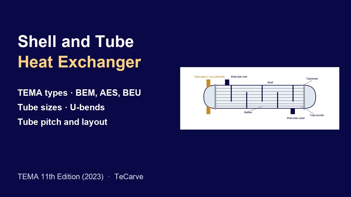
Schematic of a fixed tubesheet exchanger (TeCarve drawing, not to scale): the tube-side fluid enters and leaves through the channel; baffles route the shell-side fluid across the tube bundle.
How a shell and tube heat exchanger works
- Tube side: one fluid enters the front head (channel or bonnet), passes through the tubes, which are held at each end in a tubesheet, and leaves through the front or rear head.
- Shell side: the second fluid enters a shell nozzle and flows around the outside of the tubes; baffles support the tubes and direct this flow.
- The tubes are the heat transfer surface: their material, outside diameter, wall (gauge), length and layout set much of the exchanger’s performance, cleanability and cost.
TEMA heat exchanger types: the three-letter designation
TEMA paragraph N-1.2 designates a complete exchanger by three letters, describing in order the front-end stationary head, the shell and the rear-end head, using the types in Figure N-1.2:
| Position | Letter | TEMA description (Figure N-1.2) |
|---|---|---|
| Front end stationary head | A | Channel and removable cover |
| B | Bonnet (integral cover) | |
| C | Channel integral with tubesheet and removable cover (removable tube bundle only) | |
| N | Channel integral with tubesheet and removable cover | |
| D | Special high pressure closure | |
| Shell | E | One pass shell |
| F | Two pass shell with longitudinal baffle | |
| G | Split flow | |
| H | Double split flow | |
| J | Divided flow | |
| K | Kettle type | |
| X | Cross flow | |
| Rear end head | L | Fixed tubesheet like “A” stationary head |
| M | Fixed tubesheet like “B” stationary head | |
| N | Fixed tubesheet like “N” stationary head | |
| P | Outside packed floating head | |
| S | Floating head with backing device | |
| T | Pull through floating head | |
| U | U-tube bundle | |
| W | Externally sealed floating tubesheet |
How to read a TEMA size and type
Under TEMA N-1.1, the size is two numbers: the nominal diameter, which is the inside diameter of the shell rounded to the nearest inch (10 mm), and the nominal length, which is the tube length in inches (mm); for U-tubes it is the approximate straight length from tube end to bend tangent. The examples TEMA gives:
| TEMA designation | Exchanger (TEMA paragraph N-1.3 examples) |
|---|---|
| SIZE 23-192 TYPE AES | Split-ring floating head exchanger with removable channel and cover, single pass shell, 23 1/4 in (591 mm) inside diameter, tubes 16 ft (4877 mm) long |
| SIZE 19-84 TYPE BGU | U-tube exchanger with bonnet type stationary head, split flow shell, 19 in (483 mm) inside diameter, tubes 7 ft (2134 mm) straight length |
| SIZE 23/37-192 TYPE CKT | Pull-through floating head kettle type reboiler, stationary head integral with tubesheet, 23 in (584 mm) port diameter and 37 in (940 mm) inside shell diameter, tubes 16 ft long |
| SIZE 33-96 TYPE AFM | Fixed tubesheet exchanger with removable channel and cover, bonnet type rear head, two pass shell, 33 1/8 in (841 mm) inside diameter, tubes 8 ft (2438 mm) long |
| SIZE 17-192 TYPE NEN | Fixed tubesheet exchanger with stationary and rear heads integral with tubesheets, single pass shell, 17 in (432 mm) inside diameter, tubes 16 ft long |
Fixed tubesheet vs U-tube vs floating head
TEMA’s exchanger type selection guide (N-1.5) compares the most widely used configurations:
| Design | Examples | Advantages (TEMA N-1.5) | Limitations (TEMA N-1.5) |
|---|---|---|---|
| Fixed tubesheet, straight tubes | BEM, AEL, NEN | Generally the least expensive design; tube side accessible for cleaning | Bundle not removable, so the shell side cannot be cleaned mechanically; differential expansion between shell and tubes causes stress and an expansion joint may be required |
| Removable U-tube bundle | BEU, BKU, AEU | Economical; better shell-side access than fixed types; tubes expand freely, so no expansion joint is needed; bundle easy to replace | The inside of the bends is difficult to clean; individual tubes inside the bundle cannot be replaced |
| Removable bundle, floating tubesheet | Rear heads P, S, T, W | Straight tubes with free bundle expansion and removal; both sides easier to clean, so common in dirty services such as refineries | Generally more costly; P and W need a packing seal; S and T have a submerged bolted joint where a gasket leak can cross-contaminate the fluids |
- Expansion joints: in a fixed tubesheet exchanger, the shell and tubes reach different temperatures, and the differential expansion stresses the shell, tubes and tubesheets. TEMA describes two main types of expansion joint: thick-wall flexible shell elements and thinner bellows.
- Double tubesheets: most configurations can be built with a second tubesheet, so that a leak at the primary tube-to-tubesheet joint is contained or vented instead of reaching the other fluid. TEMA notes this adds significant cost but should be considered when a leak between the sides must be avoided.
- Shell types: the E shell (one pass) is the simplest, most common and usually least expensive. The F shell adds a longitudinal baffle for two shell passes, used when there is a temperature cross. G and H shells split the flow and are often used for thermosyphon reboilers; the K (kettle) shell has a larger diameter to leave vapour space above the bundle.
TEMA classes R, C and B
- Class R: the generally severe requirements of petroleum and related processing applications.
- Class C: the generally moderate requirements of commercial and general process applications.
- Class B: chemical process service.
Unless otherwise specified, TEMA requires the individual vessels to comply with ASME Boiler and Pressure Vessel Code, Section VIII, Division 1 (RCB-1.1.3). The mechanical standards apply to exchangers up to 100 in (2500 mm) inside diameter, a 3,000 psi (21,000 kPa) design pressure and a nominal diameter × design pressure product of 100,000 in·psi (RCB-1.1.1).
Heat exchanger tube sizes: length, OD and gauge
Tube length (RCB-2.1): commonly used lengths for straight and U-tube exchangers are 96 (2400), 120 (3000), 144 (3600), 192 (5000) and 240 (6000) in (mm); other lengths may be used.
Tube diameters and gauges (Table RCB-2.2.1): the common outside diameters and wall gauge ranges for bare tubes. TEMA notes that other diameters and gauges are acceptable, that wall thickness shall be specified as either minimum or average, and that tube characteristics are given in Table D-7 (see the tube gauge chart (BWG) for the wall of each gauge).
| Tube OD, in | Tube OD, mm (TEMA) | Copper and copper alloys, BWG (mm) | Carbon steel, aluminum and aluminum alloys, BWG (mm) | Other alloys, BWG (mm) |
|---|---|---|---|---|
| 1/4 | 6 or 6.35 | 27–18 (0.4–1.2) | – | 27–18 (0.4–1.2) |
| 3/8 | 8, 9.53 or 10 | 24–18 (0.5–1.2) | – | 24–18 (0.5–1.2) |
| 1/2 | 12, 12.7 or 14 | 22–12 (0.7–2.8) | – | 22–12 (0.7–2.8) |
| 5/8 | 15, 15.88, 16 or 18 | 20–10 (0.9–3.4) | 18–10 (1.2–3.4) | 20–10 (0.9–3.4) |
| 3/4 | 19.05 or 20 | 20–8 (0.9–4.2) | 16–8 (1.6–4.2) | 18–8 (1.2–4.2) |
| 7/8 | 22 or 22.23 | 20–8 (0.9–4.2) | 16–8 (1.6–4.2) | 18–8 (1.2–4.2) |
| 1 | 25 or 25.4 | 20–8 (0.9–4.2) | 16–8 (1.6–4.2) | 18–8 (1.2–4.2) |
| 1 1/8 | 28, 28.58 or 30 | 20–7 (0.9–4.5) | 14–7 (2.0–4.5) | 20–7 (0.9–4.5) |
| 1 1/4 | 31.75 or 32 | 20–7 (0.9–4.5) | 14–7 (2.0–4.5) | 20–7 (0.9–4.5) |
| 1 1/2 | 38, 38.1 or 40 | 16–7 (1.6–4.5) | 14–7 (2.0–4.5) | 16–7 (1.6–4.5) |
| 2 | 50, 50.8 or 55 | 14–7 (2.0–4.5) | 14–7 (2.0–4.5) | 14–7 (2.0–4.5) |
| 2 1/2 | 60, 63.5 or 65 | 14–7 (2.0–4.5) | 14–7 (2.0–4.5) | 14–7 (2.0–4.5) |
| 3 | 70, 75 or 76.2 | 14–7 (2.0–4.5) | 14–7 (2.0–4.5) | 14–7 (2.0–4.5) |
U-tubes: wall thinning at the bend
When U-bends are formed, the wall at the outer radius thins. Unless the minimum wall in the bend can be otherwise guaranteed, TEMA RCB-2.3.1 requires the wall before bending to be checked with: to = t1 × [1 + do / (C × D)], where t1 is the minimum wall calculated by Code rules for a straight tube at the same pressure and temperature, do is the tube OD, D is the mean diameter of the bend (twice the mean bend radius) and C is a thinning constant.
- C = 2 is typical for carbon steel, low alloy, ferritic stainless, austenitic stainless, other relatively non-work-hardening materials and copper alloys.
- C = 1 is typical for martensitic stainless, duplex stainless, super austenitic stainless, titanium, high nickel alloys and other work-hardening materials.
- Flattening at the bend shall not exceed 10% of the nominal tube OD; for bends with D below 4 do, flattening may exceed 10% for highly work-hardening material or when the straight tube wall is below do/12.
- Example: a 3/4 in (19.05 mm) OD austenitic stainless tube (C = 2) needing a 0.049 in straight-tube wall, bent to a 3 in mean bend diameter, needs 0.049 × (1 + 0.75 / 6) = 0.055 in before bending, so the next standard gauge up, 16 BWG (0.065 in), would be selected.
Cold work in forming U-bends may cause embrittlement or susceptibility to stress corrosion in certain materials and environments; heat treatment may be performed by agreement between manufacturer and purchaser (RCB-2.3.3).
Tube layout and tube pitch
TEMA Figure RCB-2.4 shows four standard tube patterns, named by the angle to the shell-side flow: triangular (30°), rotated triangular (60°), square (90°) and rotated square (45°). Triangular patterns should not be used when the shell side is to be cleaned mechanically; in removable bundle units with mechanical tube cleaning, square-pattern tube lanes should be continuous.
| TEMA class | Minimum tube pitch (centre-to-centre) | Cleaning lanes when mechanical tube cleaning is specified |
|---|---|---|
| R (R-2.5) | 1.25 × tube OD | Minimum 1/4 in (6.4 mm) |
| C (C-2.5) | 1.25 × tube OD; may be reduced to 1.20 × OD for tubes 5/8 in (15.875 mm) OD or less with expanded-only tube-to-tubesheet joints | – |
| B (B-2.5) | 1.25 × tube OD | Minimum 3/16 in (4.8 mm) for shells 12 in (305 mm) or less; 1/4 in (6.4 mm) for larger shells |
Stainless steel tubes for shell and tube exchangers
- Seamless: ASTM A213 / ASME SA213 covers seamless ferritic and austenitic alloy steel boiler, superheater and heat exchanger tubes.
- Welded: ASTM A249 / ASME SA249 covers welded austenitic steel boiler, superheater, heat exchanger and condenser tubes.
- Ordering: state OD, wall (and whether minimum or average), length or U-bend schedule, grade and specification; for the tube-to-tubesheet side, see tube sheet for heat exchangers.
More charts and standards guides are listed under technical resources.
Source: TEMA, Standards of the Tubular Exchanger Manufacturers Association, 11th Edition (2023): Section 1 (N-1, N-1.5, Figure N-1.2) and Section 5 (RCB-1.1, RCB-2.1 to RCB-2.4, R/C/B-2.5, Table RCB-2.2.1). TEMA requirements depend on the class and the contract; the purchaser and fabricator may agree documented exceptions.